Showing posts with label Styles. Show all posts

Tuesday, July 21, 2009

Civil 3D 2010 Style Creation Wizard


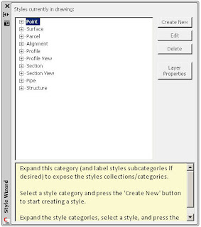
Recently a new extension called the "Style Creation Wizard" was made available. It is intended for small companies (1-5 seats) in order to help them create fundamental styles, for the more commonly used object types (see image above), very easily.

The Style Creation Wizard will, in a simple interface, walk a user through a few screens that will generate a new simple style from their responses for layers, colors, fonts, linetypes, etc. A detailed understanding of the actual Civil 3D 2010 styles creation process is not needed, and many of the needed styles when starting with Civil 3D can be created by this wizard.

So if you or your organization...

...is having difficulty defining needed styles or
...can't afford to hire someone to create needed styles or
...does not want to use the out of the box layers (National CAD Standards based)

...then you should try this extension.

Instructions for use:

Download Setup.zip-1.zip

Installation:
Download the attached “Setup.zip-1.zip” file to your machine (some may have to remove the .txt extension depending upon browser).
Extract the files from the zip file to a folder.
Double click on the “Setup.exe” file to install

Execution:
Launch Civil 3D and type the command AeccXStyleWizard on the command line.
Follow the specific instructions detailed at each step of the style creation process.

Lastly, as users become more capable with the style creation process, these newly created styles can then be modified through traditional means and made more sophisticated.

Be Better! ...be a wizard at creating styles.

Thursday, February 15, 2007

Sometimes Feature Lines Have No Style

Did you know that feature lines do not have to have a style applied to them? That makes them somewhat unique among Civil 3D objects.

In the "Create Feature Lines" dialog box we can uncheck the "Style" check box (see image). The feature line will now be place on the layer specified but will not have a style applied to it. Thus, we will not be able to apply a different style to it. It will take on the color of the layer. Although we can assign color directly to it from the properties toolbar.
All of this, though typical of AutoCAD, is very unusual for Civil 3D.

Tuesday, January 23, 2007

Read the Labels

I have now been able to provide "labels" for the majority of the almost 400 posts of this blog.

You will notice at the bottom of most posts what Blogger terms "labels". Other applications might use the term tags. If you pick on a "label" all blog posts that have similar "labels" will be displayed. I accomplished this relatively quickly and not with a fine-tooth comb. So there may be some posts that are not perfectly "label"ed.

This was worth the effort because this can be a good method to find all posts that have to do with a particular subject, such as Vault or Profiles etc.

Give it a try, see if it helps. Feel free to comment about any posts or "labels".

I will add some of the current "labels" to this post, to kick start the process.

Wednesday, November 15, 2006

Civil 3D 101 - The First Decision

Things seem to be turning a corner. Many organizations are making their first forays into using Civil 3D. They are perhaps hearing of others having success with their efforts, however small, with Civil 3D.

So how does one begin? With Training.

No, how does one begin to use the product? Oh, well once we launch Civil 3D 2007 we have to begin a new drawing preferably from a template. Our chooses are:

_Autodesk Civil 3D (Imperial) NCS Base.dwt - Contains one, and typically only one, style named BASIC for every style-able object. (221 KB)

_Autodesk Civil 3D (Imperial) NCS Classic.dwt - Contains many styles per style-able object. Contains certain styles that mimic Land Desktop as much as possible. (433 KB)

_Autodesk Civil 3D (Imperial) NCS Extended.dwt - Contains many styles per style-able object. (430 KB)

All styles use layers based on the National CAD Standards.

If no custom styles are available I tend to start with the third template.

Oh, I did not mention that there are three equivalent templates for METRIC drawing.

Monday, October 30, 2006

3 Line Profiles

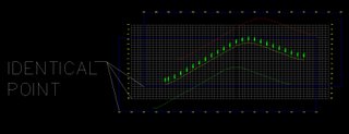
One of the most important items in the creation of "Plan and Profile Construction Documents" in Southern California, and other locations, is what we refer to as a three line profile. Although, these are likely different than what others consider three line profiles. Why? Because the right and left profiles are vertically offset from the main profile (typically centerline profile) by some vertical clearance (see image below).


I recently demonstrated to some individuals (including Autodeskers) how I create this type of three line profiles using Autodesk Civil 3D.

The ability is summed up by placing three profile views directly on top of one another (they have the same insertion point and occupy the same exact space). The key is that these three profile views have different datum which will create the required vertical offset that I mentioned.


This technique in conjuction with my last post about design profile views vs. construction document profile views allows me to create a three line profile (So. Cal. style) that very exactly matches the construction document standard requirements.

In the above example the three profile views use datums of 95 (which will generate the lower of the three profiles), 85 (to generate the middle profile placement), and 75 (which will specify the upper profile location).

I have also been known to get slightly creative with the profile view styles so that I can select one profile view quickly out of the three that lie on top of one another. In the above example this was done by placing labels above, left and/or right, and below on the approriate/corresponding profile view. Look closely each profile view only has one set of labels. This can also be done by turning off the axis or the horizontal and vertical grid lines (whatever makes most sense to the group of users).

This is another example of how with a little creativity we can take advantage of the tremendous flexibility of Civil 3D to accomplish what we need.

p.s. I would like to hear from any regions (cities, counties, states, countries) that have similar requirements.

Friday, October 27, 2006

Multiple Contour Labels

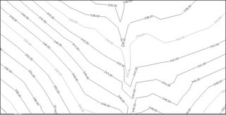
We here at KETIV Technologies recently received an inquiry as to whether or not it was possible to label contours lines with many labels at once, similar to how Land Desktop does it. The following information was prepared and contributed by Daniel Granillo, a co-worker here at KETIV.

Create Multiple Contour Labels like in Land Desktop using Civil 3D
Procedure:
1. Click Surfaces menu > Labels > Add Contour Labels
2. On the "Create Contour Labels" toolbar, select "Label Multiple Group Interior"

Note: This will enable the Multiple Group Interior edit box where you enter the desired spacing interval.

3. Enter a desired distance for the spacing interval in the field provided

4. Select a start point and endpoint for the contour label line.
5. Repeat Step 4 as needed
6. Press Enter to end the label creation process.

Tip: After creating your contour labels, you may want to turn-off the label line layer and/or make it non-plot-able (By default the contour label lines are placed on the DEFPOINTS layer).

Thanks Daniel I am sure this will help.

Monday, October 23, 2006

Civil 3D - SP3 Update

Just a reminder that there will be a Service Pack 3 for Civil 3D 2007. It is expected in the next two weeks. We have been told that it will...

Restore non-projects shortcuts (with this some will choose to not implement Vault)
Performance improvements (such as 2X faster corridor processing, 5X faster contour label regen and more).
Includes most recent Service Packs for AutoCAD® 2007, Autodesk Map® 3D 2007, and Autodesk® Vault 5.

Monday, October 09, 2006

A.C.E.S. Landed


Last Thursday evening (October 5, 2006) the Autodesk Civil Engineering Solutions (A.C.E.S.) User Group of Southern California held their inaugural meeting at the University Marriott in Fullerton, California. There were employees present from over a dozen engineering firms and several municipalities. By all accounts it was a great success. The intended goals of Share, Network, Learn seemed to be well addressed during this first meeting.

The evening began with dinner. Then Pete Kelsey, Autodesk Technical Evangelist, presented an "Industry Overview" (where have we been, where are we, and where are we headed?).

I did a "Technical Presentation" which was titled "Civil 3D on a Dime". Intended for organizations that have not yet cracked open the Civil 3D box. This section covered Civil 3D capabilities that we can use with very little or no training/investment, and take advantage of Autodesk Civil 3D 2007 to support whichever application we may use currently. These capabilities included taking data from Land Desktop into Civil 3D in order to do...

--Earthwork Volume Calculations (2 commands, 10 steps, 45 seconds)
--Translate and Rotate a Surface (4 Commands, 10 steps)
--Parcel(s) Lot Line Adjustment (3 commands, 11 steps)
--Create Geometry for an Alignment (2 commands, 8 steps)
--Renumber Parcels (2 commands 12 steps)

KETIV Technologies gave everyone in attendance a CD with custom styles and expressions to jumpstart the use of these items in Civil 3D. The evening ended with an open forum segment and announcements.

If the first meeting is any indication, there will be lots of benefits to members of this user group. The next meeting is scheduled for Thursday January 11 (location to be determined). Mark the date on your calendar, and invite your co-workers. This is a free and easy way to get information about our industry and the applications that we use.

Monday, August 28, 2006

Coming Soon - Civil 3D Community


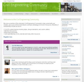
Autodesk is about to open a new section of their website. It is intended specifically for the Civil Engineering Community, which also happens to be the title. There visitors will find sections titled...

Tips & Training - tips, tricks, tutorials, training, how-tos, and workarounds
Content Sharing - area for sharing templates, styles, reports and utilities
Blogs - Two NEW Autodesk blogs** and links to many existing blogs
Discussions - links to existing peer-to-peer groups
Online Resourses - links to C.E. sites: jobs, 3rd party apps, directories
My Network - Establish industry contacts, meet users
Events - links to user groups, reseller events, seminars, and workshop

A similar site has existed for the Manufacturing Community and has been quite successful. I have interacted with this new site and know that it will become a very important resource for us (the Civil 3D user community). I look forward to it going live soon (hopefully within two weeks).

** The two NEW Autodesk Blogs are "The Dave and Dan Show" Dave Simeone, Civil 3D Product Manager, and Dan Philbrick, Civil 3D Development Manager, will have their own forum, and "Wicked Cool Stuff" by Anthony Governanti, Civil 3D Technical Marketing Manager. This site may cause hysteria among Anthony's fan club members.

Wednesday, August 23, 2006

The Leader has a Tail


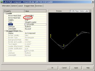
One of the items I clearly recall requesting as a wishlist item involved dragged state leaders for labels that are oriented at 90 degrees (see the 1st and 3rd labels in the image). These two labels have horizontal components at the end of the leader (I will call it a tail). I want that tail to either be oriented the same direction as the label or to not be present at all (like the middle label in the image).

The middle label does not contain this tail. Why?

This was all re-awakened by a discussion in the Newsgroups recently and they came up with the exact same explanation we have been offering. Here it is...

The following discussion is only possible when we do not want an arrowhead as a part of the dragged state leader like the left two labels.

There are two ways to make the arrowhead of the dragged state leader disappear.

1. The first is to set the Leader Arrow Head Style in the dragged state leader to "None". This produces the left most example. Not what I want to see.


2. the second method is to set the Leader Arrow Head Size to zero. This will not only make the arrowhead invisible it has the added effect of removing the tail to the leader (middle label).


It turns out the Leader Arrow Head Size is directly related to the size to the tail (some have called this a jog or a kink). The bigger the value the bigger the tail.

Tuesday, August 15, 2006

The Number 331

By our count 331 is how many styles are in the...

_Autodesk Civil 3D (Imperial) NCS Extended.dwt

How many styles are in your custom template?

Note: Our current KETIV Technologies drawing template contains approximately 540 styles.

Having custom styles that exactly represent Civil 3D objects and/or their annotation as they need to appear for final construction documents is likely the single most important factor that contributes to the positive satisfaction of users with Civil 3D.

Allow me the clarify what that means...

if appropriate, specific styles are available, they can generally be easily applied; and because of the dynamic nature of Civil 3D, user input can end with the modification of objects (such as an alignment). The annotation will update automatically and because of a custom style it will look correct.

So I ask the question again. How many styles are in your custom template?

Thursday, August 03, 2006

Civil 3D - SP2 Coming Soon

Service Pack 2 for Civil 3D 2007 will likely be available sometime next week. It should include Civil 3D 2K7 SP1A, and Map 2K7 SP1 & SP2.

Issues Resolved in Autodesk Civil 3D 2007 Service Pack 2

General

When closing the program, you no longer receive an error message after using the Object Property Manager.

Using the UNDO command after deleting or inserting an elevation point no longer causes the program to close unexpectedly.

Alignments

Version 2006 drawings that contain a Spiral Curve Spiral with the curve radius set to zero can now be migrated to version 2007 and the Spiral Curve Spiral is correctly displayed.

An issue with alignment station equations has been resolved and the station equation labels now display expected results.

Corridor

When pasting surfaces, dynamic corridor surfaces are filtered out of the selection set to avoid a situation dependency. You can create non-dynamically linked corridor surfaces to paste into an existing surface.

Using the DaylightStandard subassembly, you can create a corridor model with a horizontal slope limit and the material thickness will be applied to the horizontal links. Previously the material thickness was not applied to the horizontal links.

Changing a style of an exported corridor surface no longer causes the program to close unexpectedly.

When you specify corridor sections at Superelevation Critical Stations (from the Frequency To Apply Assemblies dialog box) the sections are now added.

Grading

Points and Elevations are now displayed accurately in the Elevation Editor.

There is improved performance using the Weed command on a feature line that was created from a polyline.

Using the Fillet command on feature lines no longer causes the program to close unexpectedly.

There is improved performance when using the Fit Curve command.

An issue with using Feature Line commands in multiple drawings has been resolved.

Using the Weed command now removes the expected points when using a weeding factor of 3D Distance. Previously not all the points that met the weeding factor were removed and all other points were removed.

Using the UNDO command after moving a grading object to a site no longer causes the program to close unexpectedly.

The maximum range for slope patterns is now displayed correctly. Previously, the slope pattern was displayed even though it was outside of the maximum range.

Elevation point z values are recognized when you add a PI to a feature line.

Entering the elevation difference on a new feature line no longer causes the Draw Feature Line command to end.

Creating a grading transition between mixed surface and elevation or distance targets no longer causes the program to close unexpectedly, however this will not result in creating a grading object because Civil 3D cannot find a valid solution for these conditions.

Labels

Using the Parcel Create by Slide Bearing command no longer causes the program to close unexpectedly when the parcel label styles contain custom expressions.

Duplicate entries are no longer created in parcel tables when you insert a new line.

Issues with parcel labels not erasing correctly have been resolved. The program no longer closes unexpectedly when using the erase command on multiple parcel labels. Labels are not redisplayed after using the erase command and then saving the drawing.

The direction arrow component type has been added to the general line label styles.

LandXML

Error messages are no longer displayed when you close a drawing after using the Export LandXML command.

When exporting multiple corridor models using the Export LandXML command the program no longer closes unexpectedly.

Parcels

The UNDO command produces expected results after using grip edits on parcels and no longer causes the program to close unexpectedly.

The UNDO command produces expected results after moving a parcel to another site and no longer causes the program to close unexpectedly.

An issue with converting a closed polyline to a parcel has been resolved.

Using grip edits on parcel lines displays expected results.

An issue with saving user defined properties in a .dwt file has been resolved.

There is improved performance when using the REGEN command for parcels.

Pipes

A set sump depth rule has been added. This rule is not added by default, but can be added to the structure rule set for use during junction structure creation (layout) or by changing all junction structure sump depths at once using the Apply Rules command.

In the Part Builder command, you can use Cyrillic and Asian characters in Catalog chapter names and part names.

When using the Change Flow Direction command, flow arrows are now displayed correctly.

Deleting structures no longer causes the program to close unexpectedly.

There is improved performance when opening version 2006 drawings that contain structure styles. The program no longer forces version 2006 drawings that contain structure styles to display the boundaries as solid.

There is improved performance when using pipe network references.

Points

An issue with editing Point Label Styles from the Point Panorama view has been resolved.

Points can no longer be selected in a viewport when they are on a layer that is frozen for that viewport.

Profiles

The correct information is now displayed in horizontal geometry bands for radius and curvature.

The pipe network band node in the profile view is now displayed in the first drawing you open. Previously, the first drawing you opened in a new session would be missing the node and you had to close and re-open the drawing.

Using the UNDO and REDO commands after deleting a sub-entity from the profile view no longer causes the program to close unexpectedly.

Performing station editing in multiple layout profiles no longer produces an error message.

Project Management

The Migrate Pre-Civil 3D Project command now creates the correct folder structure in the project.

Prospector

The program no longer closes unexpectedly when you close a drawing while the item previews are displayed in Prospector.

The Zoom To command zooms to the correct location after setting the UCS.

Surfaces

Contour smoothing no longer creates segments of zero length on closed contours. Previously the program would close unexpectedly when opening a drawing in which this occurred.

The Smooth Contours command no longer causes gaps in the contour display.

Issues with surface styles have been resolved. The program no longer closes unexpectedly when a surface is created that does not have an assigned style.

Surface labels display the correct values for Surface Slope Horizontal Distance.

The program no longer closes unexpectedly when using the Paste Surface command.

Creating Quick Profiles from a surface no longer causes the program to close unexpectedly.

An issue with the display of render masks has been resolved.

Survey

There is improved performance when importing field book files.

Using the Browse for Folder dialog box when specifying an equipment database path now returns the expected result and no longer causes the program to close.

The MCS survey figure command now starts the multipoint curve at the first point number following the command and ends correctly when other curve commands are processed.

An error message is now displayed stating that the file cannot be opened if you attempt to export a field book file to a network address where you do not have write access. The program no longer closes unexpectedly.

The Show Properties command for control points, non-control points, and directions now displays the properties in the item list view.

After inserting survey points into the drawing, using the Zoom To command from the Prospector shortcut menu for Points or Point Groups now returns correct results.

The program no longer closes unexpectedly when you attempt to close the Traverse Editor.

When using the Traverse Analysis command the Angle error now displays correctly for direction start and end traverse.

The Zoom To and Pan To commands on the Survey collection shortcut menus now return expected results.

The Browse To Observation command now returns expected results.

Changing values for the Interactive Graphics in the User Settings no longer closes the panorama view.

The Equipment Database item view list no longer closes when you right click on an Equipment item, in the list and select Make Current.

Editing Latitude and Longitude values for control points now returns the expected results for the Easting and Northing.

This Service Pack also includes resolution for the following AutoCAD issue:
An issue with slow performance has been improved when you open drawings that contain large numbers of blocks.

Wednesday, August 02, 2006

Tips & Tricks from the UK

Jack Strongitharm, Autodesk Civil 3D Technical Sales Manager (UK and Ireland), reminded me to look at the Tips and Tricks page on the Autodesk UK site.

There are several worthwhile entries on this page such as:

Using Dynamic Labels when designing an Alignment
Plain Text to Surface
Combine two terrain models
Analyzing terrian using styles
image draping on Autodesk Civil 3D Surface Onjects
General tips
Assembly Offsets
Work faster with models and files in Autodesk Civil 3D


Theses tips were created by Autodesk's Northern European team, which in addition to Jack, includes Ove Cervin and Chris Berends. Thanks for passing this along Jack.

Note: Flash player and/or Shockwave player may be needed to view certain tips.

Monday, July 31, 2006

Point Label Size Workaround

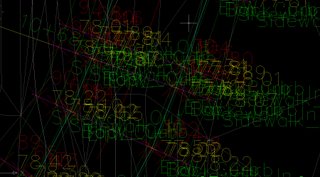
In Land Desktop whenever we encountered a scenario like the following image...

where points markers and/or point labels overlapped we could insert the points in such a ways so as they resize themselves to a percentage of the screen size.

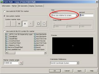
Gregory Newland recently asked in the Civil 3D Discussion Group if he could get the same type of reaction from Civil 3D. He was pointed to a style setting...


that would allow him to get similar behavior from the point markers, but not the points labels (see image).


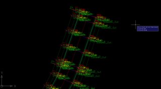
Well, Gregory came up with a workaround. He found that if he maximizes a viewport while in a layout he would get very similar behavior as to what he was accustomed to from Land Desktop. He could zoom around, do the REGEN command and the point labels would also resize themselves per the current zoom magnification (see image).


This gave him the behavior he sought.

At this point some of you will be asking "How do you maximize a viewport?" Like most things there are many ways. These may include double-clicking or the right mouse button, but, the simplest to remember is to use the "Maximize Viewport" button on the status bar (see image).


Once maximized press this button again to unmaximize.

By the way, it may be a good idea to create a new layout so that you will not accidentally disrupt any existing viewports.

This process is an example of how a little out of the box thinking can provide users with tools, steps, or prcedures that they find useful. Additionally this demonstrates the value of the Discussion Groups. The insight of one (usually gained through blood, sweat, tears and determination) can benefit many.

Thanks Gregory for sharing!

Friday, July 21, 2006

Dave & Dan Show co-Starring Anthony a Big Hit!

Today's Civil 3D webcast titled "Dave and Dan Show" was worthwhile. Dave Simeone, Civil 3D Product Manager, and Dan Philbrick, Civil 3D Development Manager along with Anthony Governanti ISD Technical Marketing Manager provided an excellent fast and furious (on-the-fly) Q & A session.

They attempted to answer and demonstate as many posted questions from viewers at home, I mean at work, that they could fit into one hour.

They covered subjects like...

Showing a crossing pipe in a profile
Labeling a crossing Pipe in profile
Creating ROW parcels
Renumbering parcels
Parcel display order
Using surface styles
Editing surface styles
Using the TOOLBOX (new in 2007)
They previewed a utility that should be free and available shortly
Rotating point labels
Transparent commands
Design curb return profiles (using Transparent commands)
Using the Inquiry Tool
Listing Points

Clearly a lot was covered. If you missed it, or if you blinked, Look for this webcast to be available soon among the recorded sessions.

Wednesday, July 12, 2006

Civil 3D 2007 - New White Papers

Autodesk has just published TWO new white papers. These white papers are titled...

Using Civil 3D for large subdivision design which is 21 pages in length. (Note: This paper is particularly interesting for those who have questions about how to organize project data for large projects)

Autodesk Civil 3D 2007 Styles: An Updated Guide to the Fundamentals which is 23 pages long.

Click on the title to get to the white papers download page or click the individual titles to open either white paper.

Tuesday, June 27, 2006

Civil 3D Webcasts CD Part III

Today, I received by mail two FREE CDs that I had requested from the Autodesk Website. The CDs contained recorded Civil 3D webcasts.

One of the CD I already had. It contained 24 webcasts recorded between 2/1/05 and 7/31/05. I had previously posted how to get this one and many of you did request it.

The second was BRAND NEW. It contains 18 webcasts recorded between 8/1/05 and 1/31/06. This CD also contains 6 success stories and 2 Whitepapers (Civil 3D 2006 Return On Investment and Civil 3D Styles Guide).

Click this sentence (or the title of this post) in order to request the CDs.

Friday, June 23, 2006

Service Pack 1A Revised Due Date

Dave Simeone, Autodesk Civil 3D Product Manager, stated during today's webcast that Service Pack 1A for Civil 3D 2007 is targeted to be released on Wednesday, June 28, 2006.

The other bit of news was that SP1A will not only address the Parcel Label issue introduced by Service Pack 1, but it will also include 4 or 5 other items that had not made it into SP1.

Thursday, June 22, 2006

SP1A Coming Soon & Misinformation

It seems that some users have been told to not install SP1 because it breaks "existing things that work" while attempting to fix others.

Additionally, these same people are being told that once SP1 is installed in order to install SP1A (due any day now) they will have to do a full product uninstall, reinstall, then apply SP1A.

The second item is completely incorrect. Dan Philbrick, Autodesk Civil 3D Development Manager, has stated in the Discussion Groups the following:

First Comment from Dan-
You will not have to install SP1 first. SP1A will include all of the fixes
in SP1.

If you have already installed SP1, you can apply SP1A and get the fix to the
parcel labeling scaling issue.


Second Comment from Dan-
The SP1A is going to resolve the parcel label scaling issue in Paperspace.
You will not have to remove the SP1. SP1A will apply to a computer with SP1
already installed.


Back to the first item, it is partially incorrect in that SP1A will address one item that SP1 broke. The problem created has to do with parcel labels not being visible in Layout Viewports. This was mentioned here on Monday June 19th, as was the workaround.

I believe users absolutely do benefit from installing SP1 and they can use the workaround if necessary. If SP1A comes out soon this issues will go away.

However this brings up the main reason for this post. It is difficult enough determining courses of action without getting wrong or bad information from sources that are considered trusted.

Wednesday, June 21, 2006

2007 New, Changed, and Obsolete Commands

Autodesk has posted in the knowledge base all of the following information for New, Changed and Obsolete Commands

New Commands
Command - Description

3DALIGN - Aligns objects with other objects in 2D and 3D.

-3DCONFIG - Provides a command line interface to the 3D graphics system's configuration settings.

3DDWF - Displays the Export 3D DWF dialog box.

3DFLY - "Activates fly-through mode and enables you to navigate in any direction including off the XY plane."

3DFORBIT - "Controls the interactive viewing of objects in 3D, using an unconstrained orbit."

3DMOVE - Displays the move grip tool in a 3D view and moves objects a specified distance in a specified direction.

3DROTATE - Displays the rotate grip tool in a 3D view and revolves objects around a base point.

3DWALK - Interactively changes the view of a 3D drawing so that you appear to be walking through the model.

AECTOACAD - Creates a new DWG file with all AEC objects exploded.

ANIPATH - Saves an animation along a path in a 3D model.

BREP - Removes the history from 3D solid primitives and composite solids.

CHSPACE - "Moves objects from model space to paper space, or vice versa. (Integrated Express Tool)"

CONVERTOLDLIGHTS - Converts lights created in previous releases to lights in AutoCAD 2007 format.

CONVERTOLDMATERIALS - Converts materials created in previous releases to materials in AutoCAD 2007 format.

CONVTOSOLID - Converts polylines and circles with thickness to 3D solids.

CONVTOSURFACE - Converts objects to surfaces.

COPYTOLAYER - Copies one or more objects to another layer. (Integrated Express Tool)

-COPYTOLAYER - Copies one or more objects to another layer. (Command line version)

DASHBOARD - Opens the Dashboard window.

DASHBOARDCLOSE - Closes the Dashboard window.

DISTANTLIGHT - Creates a distant light.

DWFADJUST - Allows adjustment of a DWF underlay from the command line.

DWFATTACH - Attaches a DWF underlay to the current drawing.

DWFCLIP - Uses clipping boundaries to define a subregion of a DWF underlay.

EXTERNALREFERENCES - Displays the External References palette.

EXTERNALREFERENCESCLOSE - Closes the External References palette.

FLATSHOT - Creates a 2D representation of all 3D objects in the current view.

GEOGRAPHICLOCATION - Specifies the latitude and longitude of a location.

HELIX - Creates a 2D or 3D spiral.

IMPRINT - Imprints an edge on a 3D solid.

-INTERFERE - Highlights 3D solids that overlap. (Command line version)

JOGSECTION - Adds a jogged segment to a section object.

LAYCUR - Changes the layer of selected objects to the current layer. (Integrated Express Tool)

LAYDEL - "Deletes the layer of a selected object and all objects on the layer, and then purges the layer from the drawing. (Integrated Express Tool)"

-LAYDEL - "Deletes the layer of a selected object and all objects on the layer, and then purges the layer from the drawing. (Command line version)"

LAYFRZ - Freezes the layer of selected objects. (Integrated Express Tool)

LAYISO - Isolates the layer of selected objects so that all other layers are turned off. (Integrated Express Tool)

LAYLCK - Locks the layer of selected objects. (Integrated Express Tool)

LAYMCH - Changes the layer of a selected object to match the destination layer. (Integrated Express Tool)

-LAYMCH - Changes the layer of a selected object to match the destination layer. (Command line version)

LAYMCUR - Makes the layer of a selected object current. (Renamed AI_MOLC)

LAYMRG - Merges selected layers onto a destination layer. (Integrated Express Tool)

-LAYMRG - Merges selected layers onto a destination layer. (Command line version)

LAYOFF - Turns off the layer of the selected object. (Integrated Express Tool)

LAYON - Turns on all layers. (Integrated Express Tool)

LAYTHW - Thaws all layers. (Integrated Express Tool)

LAYULK - Unlocks the layer of a selected object. (Integrated Express Tool)

LAYUNISO - Turns on layers that were turned off with the last LAYISO command. (Integrated Express Tool)

LAYVPI - Isolates an object's layer to the current viewport. (Integrated Express Tool)

LAYWALK - Dynamically displays layers in a drawing. (Integrated Express Tool)

LIGHTLIST - Opens the Lights in Model window to add and modify lights.

LIGHTLISTCLOSE - Closes the Lights in Model window.

LIVESECTION - Turns on live sectioning for a selected section object.

LOFT - Creates a 3D solid or surface by lofting through a set of two or more curves.

MATERIALATTACH - Attaches materials to objects by layer.

MATERIALMAP - Displays a material mapper grip tool to adjust the mapping on a face or an object.

MATERIALS - "Manages, applies, and modifies materials."

MATERIALSCLOSE - Closes the Materials window.

PLANESURF - Creates a planar surface.

POINTLIGHT - Creates a point light.

POLYSOLID - Creates a 3D polysolid.

PRESSPULL - Presses or pulls bounded areas.

PYRAMID - Creates a 3D solid pyramid.

RENDERCROP - Selects a specific region (crop window) in an image for rendering.

RENDERENVIRONMENT - Provides visual cues for the apparent distance of objects.

RENDERPRESETS - "Specifies render presets, reusable rendering parameters, for rendering an image."

RENDERWIN - Displays the Render Window without invoking a render task.

RPREFCLOSE - Closes the Advanced Render Settings palette if it is displayed.

SECTIONPLANE - Creates a section object that acts as a cutting plane through a 3D object.

SPOTLIGHT - Creates a spotlight.

SUNPROPERTIES - Opens the Sun palette and sets the properties of the sun.

SUNPROPERTIESCLOSE - Closes the Sun Properties window.

SWEEP - Creates a 3D solid or surface by sweeping a 2D curve along a path.

THICKEN - Creates a 3D solid by thickening a surface.

VISUALSTYLES - Creates and modifies visual styles and applies a visual style to a viewport.

-VISUALSTYLES - Creates and modifies visual styles and applies a visual style to a viewport. (Command line version)

VISUALSTYLESCLOSE - Closes the Visual Styles Manager.

VSCURRENT - Sets the visual style in the current viewport.

VSSAVE - Saves a visual style.

WALKFLYSETTINGS - Specifies walk and fly settings.

XEDGES - Creates wireframe geometry by extracting edges from a 3D solid or surface.


Changed Commands -
Command - Description

3DCONFIG - Provides 3D graphics system configuration settings.

3DORBIT - Controls the interactive viewing of objects in 3D.

3DPAN - Starts the interactive 3D view and enables you to drag the view horizontally and vertically in a perspective view.

3DSWIVEL - Changes the target of the view in the direction that you drag.

3DZOOM - Zooms in and out in a perspective view.

ALIGN - Aligns objects with other objects in 2D and 3D.

BOX - Creates a 3D solid box.

CAMERA - Sets a camera and target location to create and save a 3D perspective view of objects.

CHANGE - Changes the properties of existing objects.

CHPROP - Changes the properties of an object.

CONE - Creates a 3D solid with a circular or elliptical base tapering symmetrically to a point or a circular/elliptical planar face.

CUI - "Manages customized user interface elements such as workspaces, toolbars, menus, shortcut menus and keyboard shortcuts."

CYLINDER - Creates a three-sided 3D solid with a circular or elliptical base and top.

DSETTINGS - "Sets grid and snap, polar and object snap tracking, object snap modes, and Dynamic Input."

DVIEW - Defines parallel projection or perspective views by using a camera and target.

ETRANSMIT - Packages a set of files for Internet transmission.

-ETRANSMIT - Packages a set of files for Internet transmission. (Command line version)

EXPLODE - Breaks a compound object into its component objects.

EXTRUDE - Creates a 3D solid or surface by extruding an object or planar face a specified distance and direction.

FIELD - Creates a multiline text object with a field that can be updated automatically as the field value changes.

GRID - Displays a grid in the current viewport that is not plotted.

HIDE - Regenerates a three-dimensional wireframe model with hidden lines suppressed.

HLSETTINGS - Changes the display properties of lines in 2D wireframes.

IMAGE - Starts the EXTERNALREFERENCES command allowing for image management.

-IMAGE - Allows access to image options from the command line.

IMAGEADJUST - "Controls the image display of the brightness, contrast, and fade values of images."

-IMAGEADJUST - "Controls the image display of the brightness, contrast, and fade values of images. (Command line version)"

IMAGEATTACH - Attaches a new image to the current drawing.

IMAGECLIP - Uses clipping boundaries to define a subregion of an image object.

IMAGEQUALITY - Controls the display quality of images.

INTERFERE - Highlights 3D solids that overlap.

JOIN - "Joins objects to form a single, unbroken object."

LIGHT - Creates a light.

LIST - Displays database information for selected objects.

MATCHPROP - Applies the properties of a selected object to other objects.

MVIEW - Creates and controls layout viewports.

OPTIONS - Customizes the program settings.

PAGESETUP - "Controls the page layout, plotting device, paper size, and other settings for each new layout."

PLOT - "Plots a drawing to a plotter, printer, or file."

PUBLISH - Publishes drawings to DWF files or plotters.

PURGE - "Removes unused named items, such as block definitions and layers, from the drawing."

-PURGE - "Removes unused named items, such as block definitions and layers, from the drawing. (Command line version)"

QSELECT - Creates a selection set based on filtering criteria.

RECTANG - Draws a rectangular polyline.

REFCLOSE - Saves back or discards changes made during in-place editing of a reference (an xref or a block).

REFEDIT - Selects an external reference or block reference for editing.

RENDER - Creates a photorealistic or realistically shaded image of a three-dimensional wireframe or solid model.

REVOLVE - Creates a 3D solid or surface by revolving 2D objects around an axis.

RPREF - Displays the Advanced Render Settings palette for access to advanced rendering settings.

SAVEIMG - Saves a rendered image to a file.

SELECT - Places selected objects in the Previous selection set.

SHADEMODE - Starts the VSCURRENT command.

SHEETSET - Opens the Sheet Set Manager.

SLICE - Slices a solid with a plane or surface.

SNAP - Restricts cursor movement to specified intervals.

SOLIDEDIT - Edits faces and edges of 3D solid objects.

SPHERE - Creates a 3D solid sphere.

TORUS - Creates a 3D donut-shaped solid.

UCS - Manages user coordinate systems.

VIEW - "Saves and restores named views, camera views, layout views, and preset views."

-VPORTS - Creates multiple viewports in model space or paper space. (Command line version)

WBLOCK - Writes objects or a block to a new drawing file.

-WBLOCK - Writes objects or a block to a new drawing file. (Command line version)

WEDGE - Creates a five-sided 3D solid with a sloped face tapering along the X axis.

XREF - Starts the EXTERNALREFERENCES command.


Removed or Obsolete Commands -
Command - Description

3DDWFPUBLISH - Creates 3D DWF files of three-dimensional models. (Replaced with 3DDWF)

3DSOUT - Exports to a 3D Studio (3DS) file. (No replacement)

BACKGROUND - Sets up the background for your scene. (Merged with VIEW)

FOG - Provides visual cues for the apparent distance of objects. (Replaced by RENDERENVIRONMENT)

LSEDIT - Edits a landscape object. (No replacement)

LSLIB - Maintains libraries of landscape objects. (No replacement)

LSNEW - "Adds realistic landscape items, such as trees and bushes, to your drawings. (No replacement)"

MATLIB - Imports and exports materials to and from a library of materials. (Replaced by MATERIALS)

RENDSCR - Preserves the integrity of scripts. (No replacement)

REPLAY - "Displays a BMP, TGA, or TIFF image. (No replacement)"

RMAT - Manages rendering materials. (Replaced by MATERIALS)

SCENE - Manages scenes in model space. (No replacement)

SETUV - Maps materials onto objects. (Replaced by MATERIALMAP)

SHOWMAT - Lists the material type and attachment method for a selected object. (Replaced by LIST)

STATS - Displays rendering statistics. (Merged with RENDERWIN)