Showing posts with label Alignments. Show all posts

Friday, May 02, 2008

Think of the Possibilities - Dynamic Feature Lines from a Corridor

Some of you may have heard by now that Civil 3D 2009 allows for feature lines that are extracted from a corridor to be dynamically linked to the corridor (see next two images).


This ability should lead to some very creative solutions to design challenges. I absolutely look forward to seeing the inventiveness of some users with this behavior.

To get the creativity ball rolling, I spent a little time on a proof of concept that others had suggested should be possible. Here is just one example of what can be done...

In the next image, first notice that the daylighting is accomplished via a grading as opposed to a daylight subassembly (top arrows). The orange objects are feature lines that have been extracted from the corridor, and made dynamic to it. The cyan arcs (curb return) are feature lines that I added manually, that are connected to the ends of the corridor extracted feature lines. Lastly, notice that the design profile (arrow in the lower left hand viewport) is below the existing ground profile.


The next image is the result of ONE change. That one change was editing the design profile (arrow in the lower left viewport) via a grip edit to be above the existing ground profile. the rest is the result of the corridor rebuilding, the feature lines dynamically remaining linked to the corridor and those feature lines updating the cyan feature line that I add by hand (because they share a common endpoint), and of course the gradings updating as well (2 top arrows) from cut to fill.


Big deal you may be saying. Well think about it. In previous versions I would have had to modify a curb return profile as well, to ensure that the curb lines stay aligned. In this example that was not necessary, as a matter of fact there are no curb alignments, nor profiles.

Talk about a game changer. This ability should also allow us to create cross-gutter flow lines that will auto-magically remain linked without the need for extra alignments or profiles. I also created four dynamically linked feature lines on each corridor, but I could have accomplished similar with only one feature line and gradings from that one, in the curb return area.

Where once I needed 12 alignments and corresponding profiles to do a full intersection with cross-gutters and spandrells, I can do it with only two.

Just Think of the possibilities.


Be Better... Don't do things the old way!

Monday, March 05, 2007

Nothing Up My Sleeve

Just like everyone else, I have been unbelievably busy. Although, I did get to try something that has me VERY excited about the future use of Civil 3D. A product will be out shortly called Advanced Road Design CORRIDOR-EZY. Some of you may have seen it at Autodesk University. This product is developed by CADApps Australia. After learning some about it here is my progress.

Step 1: Open original drawing with about 26 Alignments (see image below).
Step 2: Press one button. 45 second later drawing contains items software recognizes as "ROADS" and creates proposed profiles for them (see image below).

Step 3: Press a second button. 1 minute 5 seconds later drawing contains all curb return alignments and proposed profiles for them as well (see image below).

Step 4: Press a third button. 2 minutes and 5 seconds later a surface exists of the entire road system in a development (see image below).

4 minutes total!

Now, I do not wish to mis-lead anyone. I have not yet addressed Knuckles or Cul-De-Sacs, which this software can address along with Roundabouts. I would want to check all proposed profiles, change widths of certain collector streets, etc. But, for 4 minutes worth of work to do 33 intersections along 26 streets this is ama-za-zing stuff.

To qualify this, remember that I gave a Knuckle and Cul-De-Sacs class at Autodesk University this past November.

With some instruction we can create true Civil 3D corridors in a fraction of the time it would take with Civil 3D alone. Using Civil 3D by itself, in my opinion, a capable person could create an intersection for scratch in about roughly 1 hour (that means about 33 hours for the example above). At just about any price this product should pay for itself in no time at all.

And imagine what this will do for those involved with preliminary design and visualization, I can not think of a better tool to do that.

Oh, and I almost forgot the most impressive thing of all. Profiles of crossing streets are linked by the software. If I raise or lower a major road... ALL CROSSING ROAD PROFILES ARE ADJUSTED TO MATCH AUTOMATICALLY! Yes, all crossing road profiles. That includes the curb return profiles. We do not have to go back and adjust them manually. How awesome is that!

You may be asking, when can we expect to see this product? I understand that it should be available just about when Civil 3D 2008 is released, near April 16, 2007. If this all sound somewhat familiar that is because this is the next incarnation of Advanced Road Design INTERSECTION which has been out for awhile.

Thank you CADApps!

Tuesday, January 23, 2007

Read the Labels

I have now been able to provide "labels" for the majority of the almost 400 posts of this blog.

You will notice at the bottom of most posts what Blogger terms "labels". Other applications might use the term tags. If you pick on a "label" all blog posts that have similar "labels" will be displayed. I accomplished this relatively quickly and not with a fine-tooth comb. So there may be some posts that are not perfectly "label"ed.

This was worth the effort because this can be a good method to find all posts that have to do with a particular subject, such as Vault or Profiles etc.

Give it a try, see if it helps. Feel free to comment about any posts or "labels".

I will add some of the current "labels" to this post, to kick start the process.

Wednesday, December 06, 2006

Want To Double Pick or Right-Click Edit?

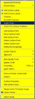
One of my favorite classes at Autodesk University 2006 (last week) was given by my friend David Garrigues. During the class he described how he had created a CUI with custom Right-Click menus (many commands per object type) and the ability to Double-Pick on an AECC object (Alignment, Surface etc.) and bring up the object's Properties Dialog Box, instead of the AutoCAD Properties Palette. This gives users of this CUI a quicker way to create, edit, interact with, and control their Civil 3D objects. The images to the left show what you see if you bring up the right-click menu while selecting a Surface and Feature Line respectively.

During the class, David mentioned that he would make this CUI available. The simplest way to do so was for him to post it in the "Content Sharing" section of the "Civil Engineering Community" website. It is located in the "Utilities" area of "Content Sharing". It is titled:

"Double and Right Click CUI"


You must be registered and login to the site in order to download this CUI.

Download it and follow the instruction from the readme file to get it installed properly. I have already done so and it makes life a bunch easier.

Thanks Dave!!

Wednesday, November 08, 2006

Cul-De-Sacs Fix in SP3

Dan Philbrick, Autodesk Civil 3D Software Development Manager, mentioned in his blog, in the Civil Engineering Community, that Service Pack 3 fixes an issue that has existed when trying to design cul-de-sac corridors with arcs in the centerline alignment.

If our baseline was run around the cul-de-sac bulb entirely as one alignment and had as its target an centerline alighnment with an arc, the assemblies would not solve correctly and leave a flat teardrop shaped gap in the middle of the corridor. This did not happen if the centerline alignment was a tangent (straight).

The necessary workaround was to create two alignments around the bulb of the cul-de-sac each targeting the centerline alignment with the arc.

With the fix provide by Service Pack 3 we no longer need to create the two alignments and can accomplish this goal with one alignment if we so choose.


I went back through the ...README.htm file to see if this was mentioned. I could not find any mention of it. Either way this is a very good thing.

Too bad my Autodesk University "Cul-de-Sacs Are Not a Dead End" class handouts were already submitted. Oh well, I will just have to mention that that was fixed.

Tuesday, October 17, 2006

We Wish, Jeff Shares

Jeff Mishler, of Santa Rosa, CA, has created some lisp & VBA routines that he has made available for all to benefit from. The most recent one that I have seen addresses a request that someone had in the Civil 3D discussion group. They asked for a routine, similar to a Land Desktop command, that would "list all available point numbers". Jeff's routine named FreeNums does just that.

Jeff has also created a routine that is currently being shared in the Civil Engineering Community. The lisp routine named "Alignment Tooltips tools.lsp" turns tooltips on/off for all or selected alignments. (You have to be registered with the community in order to download this file.)

Rotate_Markers allows users to to rotate the marker and labels of selected points. (For this one you will have scroll down and find the code in order to copy and paste it and save to a .lsp file)

Lastly, the Rebuild_All_Corridors (copy and paste required here as well) routine rebuilds all selected corridors or if none are selected it rebuilds ALL corridors.

I would personally like that thank Jeff for being generous enough to share these tools, and his talents, with our entire community.

He shared with me the fact that he usually monitors the Civil 3D Wishes Discusion Group, and the fact that he looks for code/solutions/workarounds for just about every wish. So, if you have a wish for a command or capability in Civil 3D do not hesitate to ask for it in the Wishes Discussion Group. Best case someone (ie. Autodesk, Jeff, or someone him) will answer your wish. No need for a genie.

Monday, October 09, 2006

A.C.E.S. Landed


Last Thursday evening (October 5, 2006) the Autodesk Civil Engineering Solutions (A.C.E.S.) User Group of Southern California held their inaugural meeting at the University Marriott in Fullerton, California. There were employees present from over a dozen engineering firms and several municipalities. By all accounts it was a great success. The intended goals of Share, Network, Learn seemed to be well addressed during this first meeting.

The evening began with dinner. Then Pete Kelsey, Autodesk Technical Evangelist, presented an "Industry Overview" (where have we been, where are we, and where are we headed?).

I did a "Technical Presentation" which was titled "Civil 3D on a Dime". Intended for organizations that have not yet cracked open the Civil 3D box. This section covered Civil 3D capabilities that we can use with very little or no training/investment, and take advantage of Autodesk Civil 3D 2007 to support whichever application we may use currently. These capabilities included taking data from Land Desktop into Civil 3D in order to do...

--Earthwork Volume Calculations (2 commands, 10 steps, 45 seconds)
--Translate and Rotate a Surface (4 Commands, 10 steps)
--Parcel(s) Lot Line Adjustment (3 commands, 11 steps)
--Create Geometry for an Alignment (2 commands, 8 steps)
--Renumber Parcels (2 commands 12 steps)

KETIV Technologies gave everyone in attendance a CD with custom styles and expressions to jumpstart the use of these items in Civil 3D. The evening ended with an open forum segment and announcements.

If the first meeting is any indication, there will be lots of benefits to members of this user group. The next meeting is scheduled for Thursday January 11 (location to be determined). Mark the date on your calendar, and invite your co-workers. This is a free and easy way to get information about our industry and the applications that we use.

Tuesday, August 15, 2006

The Number 331

By our count 331 is how many styles are in the...

_Autodesk Civil 3D (Imperial) NCS Extended.dwt

How many styles are in your custom template?

Note: Our current KETIV Technologies drawing template contains approximately 540 styles.

Having custom styles that exactly represent Civil 3D objects and/or their annotation as they need to appear for final construction documents is likely the single most important factor that contributes to the positive satisfaction of users with Civil 3D.

Allow me the clarify what that means...

if appropriate, specific styles are available, they can generally be easily applied; and because of the dynamic nature of Civil 3D, user input can end with the modification of objects (such as an alignment). The annotation will update automatically and because of a custom style it will look correct.

So I ask the question again. How many styles are in your custom template?

Thursday, August 03, 2006

Civil 3D - SP2 Coming Soon

Service Pack 2 for Civil 3D 2007 will likely be available sometime next week. It should include Civil 3D 2K7 SP1A, and Map 2K7 SP1 & SP2.

Issues Resolved in Autodesk Civil 3D 2007 Service Pack 2

General

When closing the program, you no longer receive an error message after using the Object Property Manager.

Using the UNDO command after deleting or inserting an elevation point no longer causes the program to close unexpectedly.

Alignments

Version 2006 drawings that contain a Spiral Curve Spiral with the curve radius set to zero can now be migrated to version 2007 and the Spiral Curve Spiral is correctly displayed.

An issue with alignment station equations has been resolved and the station equation labels now display expected results.

Corridor

When pasting surfaces, dynamic corridor surfaces are filtered out of the selection set to avoid a situation dependency. You can create non-dynamically linked corridor surfaces to paste into an existing surface.

Using the DaylightStandard subassembly, you can create a corridor model with a horizontal slope limit and the material thickness will be applied to the horizontal links. Previously the material thickness was not applied to the horizontal links.

Changing a style of an exported corridor surface no longer causes the program to close unexpectedly.

When you specify corridor sections at Superelevation Critical Stations (from the Frequency To Apply Assemblies dialog box) the sections are now added.

Grading

Points and Elevations are now displayed accurately in the Elevation Editor.

There is improved performance using the Weed command on a feature line that was created from a polyline.

Using the Fillet command on feature lines no longer causes the program to close unexpectedly.

There is improved performance when using the Fit Curve command.

An issue with using Feature Line commands in multiple drawings has been resolved.

Using the Weed command now removes the expected points when using a weeding factor of 3D Distance. Previously not all the points that met the weeding factor were removed and all other points were removed.

Using the UNDO command after moving a grading object to a site no longer causes the program to close unexpectedly.

The maximum range for slope patterns is now displayed correctly. Previously, the slope pattern was displayed even though it was outside of the maximum range.

Elevation point z values are recognized when you add a PI to a feature line.

Entering the elevation difference on a new feature line no longer causes the Draw Feature Line command to end.

Creating a grading transition between mixed surface and elevation or distance targets no longer causes the program to close unexpectedly, however this will not result in creating a grading object because Civil 3D cannot find a valid solution for these conditions.

Labels

Using the Parcel Create by Slide Bearing command no longer causes the program to close unexpectedly when the parcel label styles contain custom expressions.

Duplicate entries are no longer created in parcel tables when you insert a new line.

Issues with parcel labels not erasing correctly have been resolved. The program no longer closes unexpectedly when using the erase command on multiple parcel labels. Labels are not redisplayed after using the erase command and then saving the drawing.

The direction arrow component type has been added to the general line label styles.

LandXML

Error messages are no longer displayed when you close a drawing after using the Export LandXML command.

When exporting multiple corridor models using the Export LandXML command the program no longer closes unexpectedly.

Parcels

The UNDO command produces expected results after using grip edits on parcels and no longer causes the program to close unexpectedly.

The UNDO command produces expected results after moving a parcel to another site and no longer causes the program to close unexpectedly.

An issue with converting a closed polyline to a parcel has been resolved.

Using grip edits on parcel lines displays expected results.

An issue with saving user defined properties in a .dwt file has been resolved.

There is improved performance when using the REGEN command for parcels.

Pipes

A set sump depth rule has been added. This rule is not added by default, but can be added to the structure rule set for use during junction structure creation (layout) or by changing all junction structure sump depths at once using the Apply Rules command.

In the Part Builder command, you can use Cyrillic and Asian characters in Catalog chapter names and part names.

When using the Change Flow Direction command, flow arrows are now displayed correctly.

Deleting structures no longer causes the program to close unexpectedly.

There is improved performance when opening version 2006 drawings that contain structure styles. The program no longer forces version 2006 drawings that contain structure styles to display the boundaries as solid.

There is improved performance when using pipe network references.

Points

An issue with editing Point Label Styles from the Point Panorama view has been resolved.

Points can no longer be selected in a viewport when they are on a layer that is frozen for that viewport.

Profiles

The correct information is now displayed in horizontal geometry bands for radius and curvature.

The pipe network band node in the profile view is now displayed in the first drawing you open. Previously, the first drawing you opened in a new session would be missing the node and you had to close and re-open the drawing.

Using the UNDO and REDO commands after deleting a sub-entity from the profile view no longer causes the program to close unexpectedly.

Performing station editing in multiple layout profiles no longer produces an error message.

Project Management

The Migrate Pre-Civil 3D Project command now creates the correct folder structure in the project.

Prospector

The program no longer closes unexpectedly when you close a drawing while the item previews are displayed in Prospector.

The Zoom To command zooms to the correct location after setting the UCS.

Surfaces

Contour smoothing no longer creates segments of zero length on closed contours. Previously the program would close unexpectedly when opening a drawing in which this occurred.

The Smooth Contours command no longer causes gaps in the contour display.

Issues with surface styles have been resolved. The program no longer closes unexpectedly when a surface is created that does not have an assigned style.

Surface labels display the correct values for Surface Slope Horizontal Distance.

The program no longer closes unexpectedly when using the Paste Surface command.

Creating Quick Profiles from a surface no longer causes the program to close unexpectedly.

An issue with the display of render masks has been resolved.

Survey

There is improved performance when importing field book files.

Using the Browse for Folder dialog box when specifying an equipment database path now returns the expected result and no longer causes the program to close.

The MCS survey figure command now starts the multipoint curve at the first point number following the command and ends correctly when other curve commands are processed.

An error message is now displayed stating that the file cannot be opened if you attempt to export a field book file to a network address where you do not have write access. The program no longer closes unexpectedly.

The Show Properties command for control points, non-control points, and directions now displays the properties in the item list view.

After inserting survey points into the drawing, using the Zoom To command from the Prospector shortcut menu for Points or Point Groups now returns correct results.

The program no longer closes unexpectedly when you attempt to close the Traverse Editor.

When using the Traverse Analysis command the Angle error now displays correctly for direction start and end traverse.

The Zoom To and Pan To commands on the Survey collection shortcut menus now return expected results.

The Browse To Observation command now returns expected results.

Changing values for the Interactive Graphics in the User Settings no longer closes the panorama view.

The Equipment Database item view list no longer closes when you right click on an Equipment item, in the list and select Make Current.

Editing Latitude and Longitude values for control points now returns the expected results for the Easting and Northing.

This Service Pack also includes resolution for the following AutoCAD issue:
An issue with slow performance has been improved when you open drawings that contain large numbers of blocks.

Wednesday, August 02, 2006

Tips & Tricks from the UK

Jack Strongitharm, Autodesk Civil 3D Technical Sales Manager (UK and Ireland), reminded me to look at the Tips and Tricks page on the Autodesk UK site.

There are several worthwhile entries on this page such as:

Using Dynamic Labels when designing an Alignment
Plain Text to Surface
Combine two terrain models
Analyzing terrian using styles
image draping on Autodesk Civil 3D Surface Onjects
General tips
Assembly Offsets
Work faster with models and files in Autodesk Civil 3D


Theses tips were created by Autodesk's Northern European team, which in addition to Jack, includes Ove Cervin and Chris Berends. Thanks for passing this along Jack.

Note: Flash player and/or Shockwave player may be needed to view certain tips.

Thursday, June 29, 2006

Civil 3D 2007 - Service Pack 1A Now Available

Service Pack 1A is now available for download. It includes Service Pack 1, plus it addresses additional items.

General - 1 Additional item
Alignment - 1 Additional item
Labels - 2 New items
Pipes - 2 Additional items

Wednesday, May 03, 2006

Civil 3D 2007 - Data Shortcuts


Corrected: Thanks to Josh Nelson for the comment!

Before Vault there were data shortcuts. There were two ways to use data shortcuts 1. Through the old project environment (the most common approach). 2. By manually creating, managing, and using them.

Now that projects are handled through Vault, what has happened to data shortcuts?

Well, they still exist. Although, they have changed. Because now they can only be created, managed, and used manually.

The new data shortcuts do require hands-on interaction and attention. But, this manual method is more flexible in that I do not need a project. Now don't get me wrong, in order to share project data Vault is the proper solution. But, data shortcuts have a place in our world. Typically very small projects.

By the way, data shortcuts can now be used for Pipe Networks in addition to Surfaces, Alignment, and Profiles which were always possible.

OK, how do we use them?

1. In a drawing that contains shortcut-able (I just created that word. Feel free to use it) objects click "General" > "Data Shortcuts" > "Edit Data Shortcuts...".

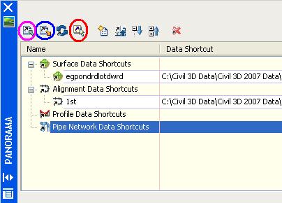
2. In the "Data Shortcuts" vista of the "Panorama" view click "Create data shortcut by selection" (4th icon, I circled it in red in the image above). Then select the object you wish use via shortcuts.

A shortcut is created but we have to export it by creating an .XML file.

3. In the "Data Shortcuts" vista of the "Panorama" view click "Export data shortcuts to file" (2nd icon, I circled it in blue in the image above). Then Name .XML file.

Now, the shortcut is available for use in another drawing. We now need to create a data reference

4. In a drawing where we wish to use a data shortcut click "General" > "Data Shortcuts" > "Edit Data Shortcuts...".

5. In the "Data Shortcuts" vista of the "Panorama" view click "Import data shortcuts to file" (1st icon, I circled it in magenta in the image above). Then select the .XML file created in step 3.

6. In the "Data Shortcuts" vista of the "Panorama" select the imported shortcut to create a reference for and then click "Create reference" (5th icon, I did not circle it in the image above).

a reference to the shortcut-ed object is then created.

We still get data synchronization messages as before. Remember this can be done without a project.

Saturday, April 15, 2006

Bootcamp Day Five - Three Homeruns

Thursday was my fifth and final day at bootcamp. It turned out to be my favorite one.

Why? Well, Autodesk hit three homeruns with me. One for each of the subjects that I covered that day.

HOMERUN #1
Pipes: The additions to pipes were excellent. New rules for both pipes and structures. Structure properties that include pipe inverts that can be edited. Rules can be reapplied at my choosing. Create a network from a pline. Create an alignment from a network. Import LDT pipe runs. Interference checking for collisions or clearance (COOL!). New grips in profile.

HOMERUN #2
Corridors: Lots here too. Many new spiral types. Constrained profiles (similar to horizontal alignments, Fixed, Floating, Free). Floating parabolic curves can now end a profile. Three new transparent commands (profile station from plan view, profile station and elevation from plan view, and profile station and elevation from plan view and point). Profile geometry point can now be labeled in plan views. Customizable markers replace hard-coded ones. Quick profiles, which can include the baseline geometry itself. Two new profile bands: Sectional data and Pipe Network data. Corridors regions can have styles (outlines). Graphical edit can be done. Individual sections can be edited. Corridor surfaces are true surfaces on Prospector tab. 16 new subassemblies. Two new tables: Total Volumes, Materials.

HOMERUN #3
General Drafting: We will now have a Toolbox tab to the Toolspace. This will include reports, but can include custom created tools. Text masking can be added to ALL labels, they can also have a draw order specified. There is now a NOTE label for any text item. We can label basic lines and curves. Reference text in labels can be created from any combination of object(s). Expressions allow us to due math computation with object data (EXCELLENT!!!). We will be able to copy label components. Drag-and-Drop styles will now prompt to Overwrite or Rename. And perhaps my favorite of all EDIT INDIVIDUAL LABEL TEXT VALUES.

It was a very useful and educational week. As you can see there is much to learn, absorb, and incorporate into our habits. That being said, I am sure glad to be home.

I'll be back soon with more detailed posts.

Wednesday, April 05, 2006

LandXML Revisited

What is Land XML? LandXML is a non-proprietary data standard created by a consortium of industry partners to share (import/export) "civil engineering data".

What type of data? Currently, LandXML 1.0, supports Cogo Points, Point Groups, Surfaces, Watersheds, Parcels, Alignments, Alignment Profiles, Alignment Cross Sections, and Pipe Networks. Shortly, 1.1 will addtionally support survey and corridors model data.

How do we use it? In Civil 3D from the "General" menu pulldown select "Import LandXML..." or "Export LandXML..."

What can we do with it? It can be used for any of the following:

1. To transfer data from a supported software application to another supported application (like LDt to Civil 3D).

2. To convert data from imperial units to metric or vice versa (automatically).

3. To globally translate/rotate coordinates (via settings).

4. To archive data at important milestones.

5. To generate reports about civil objects/data (via LandXML Reporting).

6. To allow 3D viewing of civil objects/data in a LandXML viewer (such as Autodesk Envision 8).

Six years after in was introduced it is amazing that MANY groups that would clearly benefit from the use of LandXML do not know of it's existance. Many people have dropped the ball on this one.

For example, I have used LandXML to export civil data from corrupt Civil 3D drawings and then imported the data into a clean new drawing. Problem solved.

Click on the title of this post to get to the LandXLM.org website and see examples, list of support software, and other facts.

I am revisting this topic for a few reasons. The first is because I am adding information to it. The second is because when someone does a "SEARCH THIS BLOG", via the button in the upper left hand corner, for any topic of interest, the search mechanism only goes back one year and the original post was on Feb. 14, 2005 (a little more than 1 year ago). Thirdly, because it has been one of the most viewed posts of all time (within this blog of course). Lastly, I am revisiting this subject because LandXML 1.1 is within days (weeks?) of being ratified and it will include additional capabilities.

Wednesday, March 01, 2006

Civil 3D 2007


As Autodesk introduces the NEW family of 2007 products (shipping in the next month or two) there will be lots to talk about. Here we will focus of course on Civil 3D 2007. What will be there? What will not? I will mention a few general topics today with detailed posts in the near future.

Lets begin.

One of the most obvious additions to Civil 3D is the entirely new Survey functionality and the survey observation object.

The Project environment will now be managed by the core data management capabilities of Autodesk Vault. It will allow for the sharing of:

Points
Surfaces
Alignments
Profiles
Pipe Networks (NEW)
Survey Data (NEW)

Corridors will create named surfaces directly. We will no longer have to export non-associated surfaces. We will also be able to select an existing polyline as a corridor boundary (cool). There will be new subassemblies.

Profiles will now be element-based (free, floating, fixed). This allows for similar constraints as horizontal alignments.

Grading Feature Lines will be controlled by a new set of tools which include the ability, similar to LDt, to create offsets with elevational differences.

Quick sections will be able to be created from AutoCAD objects.

We will be able to create a Pipe Network from a polyline and create an alignment from an existing pipe network. Pipe interference detection will be possible.

Styles management will include the ability to Merge, Copy, or Rename any duplicates found during drag-and-drop operations.

Labels will be able to contain data from various object types in our models. We will be able to include expressions (formulas) in a label style. The labeling of lines, arcs and polylines with style based labels will be possible. I am confident that many will appreciate that masks will be able to be added to labels to hide object behind the label.

We will be able to reset a Point's elevations based on an existing surface. Changing an individual point's rotation angle graphically will be possible.

LandXML 1.1 support for survey and corridor data will help matters.

These are just a few of the enhancements that caught my eye. These plus those found in AutoCAD 2007 and Map 3D 2007 (because Civil 3D is built on top of these products) will give us lots benefit from.

OK, that is enough for now. As I said, I hope to add comments and details in the coming days, and weeks, as time permits.

Friday, February 24, 2006

Naming Styles

OK, here is a very quick tip. Here at KETIV Technologies, as we create new styles, we use the following naming convention... we will typically begin the names with an "underbar" followed by our company initials and then the more descriptive name of the style. For example a style for an existing alignment object would be something like...

_KT Ex Align

This will accomplish three things.

1. Our styles will float to the top of the styles collection (because they are listed alphabetically).

2. We will not confuse our styles with the commonly named styles of other users.

3. Users will know where the style that they have acquired originated.

Note: We also provide a detailed description within the style that includes the initials of the creator and the date of creation.


By John Rodriguez and Angel Espinoza

Tuesday, January 24, 2006

AU 2005 Top 12 Civil Track Classes


I just received info regarding the civil track classes at AU 2005 that had the most registrants.

If you are using AU Online (click title of this post above to connect) and want to see the classes that seemed to have a fair amount of interest you may find this list useful.

I am sure that prespective AU 2006 speakers will find this list of interest as well.


And the TOP 12 are:


Autodesk University 2005
Civil Engineering

CV32-2 Essentials of Site Grading with Autodesk® Civil 3D®
CV33-1 Advanced Site Grading with Autodesk® Civil 3D®
CV14-2 Autodesk® Civil 3D® Pipes: Storm Sewer Layout & Design
CV31-2 Autodesk® Civil 3D® Pipes Workshop
CV21-2 Essentials of Road Design with Autodesk® Civil 3D® 2006
CV13-3 Best of Both Worlds: Autodesk® Land Desktop and Autodesk® Civil 3D®
CV22-2 Autodesk® Civil 3D® Corridors: Cul-de-Sacs Are Not a Dead End
CV21-3 Think Outside the Contour: Grading in 3D
CV15-2 Essentials of Points and User-Defined Properties in Autodesk® Civil 3D®
CV41-4 Top 10 Autodesk® Land Desktop Tips and Tricks
CV35-3 Programming Corridor Assemblies in Autodesk® Civil 3D®
CV34-4 Amazing Grade - How Sweet the Ground

My class CV22-2 in turns out was the 7th most highly attended class out of the 41 classes in the Civil Track. As a first-timer, I am greatful for the experience.

Thursday, October 13, 2005

Lost and Found: Panorama Window and it's Vistas

It is interesting how things occur in clumps. Coincidence? Conspiracy? Anyways, It was curious a few days ago when several users posted to discussion groups about the following issue and I received a phone call and an e-mail about the same thing.

Scenario: A user attempts to edit an alignment via the align grid view or edit a point. Both of these actions should open the "Panorama" window. The user should then see different tabs (Vistas) for the editor that they requested. Instead nothing appears to happen and the user is unable to proceed as intended.

Solution: The Panorama window was unintentionally docked. To undock it and make it visible the user should...


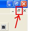
Unmaximize the drawing window. The "Panorama" window will be visible. Undock "Panorama" Window. Maximize drawing window.


Perhaps it was just a coincidence.

Friday, September 16, 2005

Name the Parts


When creating Assemblies it is a good habit to get into to name the Subassemblies components. This will eliminate confusion when it is time to "Set Logical Names".

To name a Subassembly you can...

1. Select (highlight) the Subassembly component within an Assembly and modify the "Name" field in the Properties Palette.

or you can...

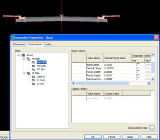
2. Select the Assembly (the centerline) Right-click and select "Assembly Properties" from the Short-cut menu. In the "Assembly Properties" dialog box select the "Construction" tab. In the Item window Right-click on an item, select "Rename" and give the item a more definitive name (see image). Repeat for every item.

Trust me when I say this will help you a great deal later.

Thursday, September 15, 2005

Zoom to or Pan to


Here is a quick tip. When working with users of Civil 3D 2006 they often forget to "Zoom to" or "Pan to".

What do I mean? On the Prospector tab of the Toolspace Pallette we can see the different objects contained within the current drawing. We can see the Parcels, Alignment, Surfaces etc. If we right-click on any of the objects, a Short-cut menu will appear and we can choose "Zoom to" which will zoom extents on the chosen object. Or, we can "Pan to" which will pan, at the current zoom magnification, to the centroid of the selected object. Which may not show us the object at high magnifications, especially with alignments.