Showing posts with label Surfaces. Show all posts

Monday, March 05, 2007

Nothing Up My Sleeve

Just like everyone else, I have been unbelievably busy. Although, I did get to try something that has me VERY excited about the future use of Civil 3D. A product will be out shortly called Advanced Road Design CORRIDOR-EZY. Some of you may have seen it at Autodesk University. This product is developed by CADApps Australia. After learning some about it here is my progress.

Step 1: Open original drawing with about 26 Alignments (see image below).
Step 2: Press one button. 45 second later drawing contains items software recognizes as "ROADS" and creates proposed profiles for them (see image below).

Step 3: Press a second button. 1 minute 5 seconds later drawing contains all curb return alignments and proposed profiles for them as well (see image below).

Step 4: Press a third button. 2 minutes and 5 seconds later a surface exists of the entire road system in a development (see image below).

4 minutes total!

Now, I do not wish to mis-lead anyone. I have not yet addressed Knuckles or Cul-De-Sacs, which this software can address along with Roundabouts. I would want to check all proposed profiles, change widths of certain collector streets, etc. But, for 4 minutes worth of work to do 33 intersections along 26 streets this is ama-za-zing stuff.

To qualify this, remember that I gave a Knuckle and Cul-De-Sacs class at Autodesk University this past November.

With some instruction we can create true Civil 3D corridors in a fraction of the time it would take with Civil 3D alone. Using Civil 3D by itself, in my opinion, a capable person could create an intersection for scratch in about roughly 1 hour (that means about 33 hours for the example above). At just about any price this product should pay for itself in no time at all.

And imagine what this will do for those involved with preliminary design and visualization, I can not think of a better tool to do that.

Oh, and I almost forgot the most impressive thing of all. Profiles of crossing streets are linked by the software. If I raise or lower a major road... ALL CROSSING ROAD PROFILES ARE ADJUSTED TO MATCH AUTOMATICALLY! Yes, all crossing road profiles. That includes the curb return profiles. We do not have to go back and adjust them manually. How awesome is that!

You may be asking, when can we expect to see this product? I understand that it should be available just about when Civil 3D 2008 is released, near April 16, 2007. If this all sound somewhat familiar that is because this is the next incarnation of Advanced Road Design INTERSECTION which has been out for awhile.

Thank you CADApps!

Tuesday, January 23, 2007

Read the Labels

I have now been able to provide "labels" for the majority of the almost 400 posts of this blog.

You will notice at the bottom of most posts what Blogger terms "labels". Other applications might use the term tags. If you pick on a "label" all blog posts that have similar "labels" will be displayed. I accomplished this relatively quickly and not with a fine-tooth comb. So there may be some posts that are not perfectly "label"ed.

This was worth the effort because this can be a good method to find all posts that have to do with a particular subject, such as Vault or Profiles etc.

Give it a try, see if it helps. Feel free to comment about any posts or "labels".

I will add some of the current "labels" to this post, to kick start the process.

Wednesday, December 06, 2006

Want To Double Pick or Right-Click Edit?

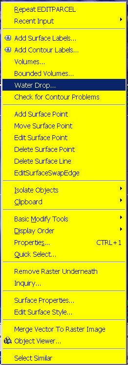
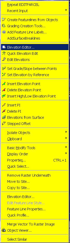
One of my favorite classes at Autodesk University 2006 (last week) was given by my friend David Garrigues. During the class he described how he had created a CUI with custom Right-Click menus (many commands per object type) and the ability to Double-Pick on an AECC object (Alignment, Surface etc.) and bring up the object's Properties Dialog Box, instead of the AutoCAD Properties Palette. This gives users of this CUI a quicker way to create, edit, interact with, and control their Civil 3D objects. The images to the left show what you see if you bring up the right-click menu while selecting a Surface and Feature Line respectively.

During the class, David mentioned that he would make this CUI available. The simplest way to do so was for him to post it in the "Content Sharing" section of the "Civil Engineering Community" website. It is located in the "Utilities" area of "Content Sharing". It is titled:

"Double and Right Click CUI"


You must be registered and login to the site in order to download this CUI.

Download it and follow the instruction from the readme file to get it installed properly. I have already done so and it makes life a bunch easier.

Thanks Dave!!

Friday, October 27, 2006

Multiple Contour Labels

We here at KETIV Technologies recently received an inquiry as to whether or not it was possible to label contours lines with many labels at once, similar to how Land Desktop does it. The following information was prepared and contributed by Daniel Granillo, a co-worker here at KETIV.

Create Multiple Contour Labels like in Land Desktop using Civil 3D
Procedure:
1. Click Surfaces menu > Labels > Add Contour Labels
2. On the "Create Contour Labels" toolbar, select "Label Multiple Group Interior"

Note: This will enable the Multiple Group Interior edit box where you enter the desired spacing interval.

3. Enter a desired distance for the spacing interval in the field provided

4. Select a start point and endpoint for the contour label line.
5. Repeat Step 4 as needed
6. Press Enter to end the label creation process.

Tip: After creating your contour labels, you may want to turn-off the label line layer and/or make it non-plot-able (By default the contour label lines are placed on the DEFPOINTS layer).

Thanks Daniel I am sure this will help.

Monday, September 11, 2006

The Tips Are Coming In

There are now 20 tips for Civil 3D in the Civil Engineering Community. I have found these are helpful for learning or recalling tips and tricks. As with just about everthing in the community pages, we can rate the usefulness of an item with a 5 star rating system.

Here are a few tip titles (along with their current ratings):

Increase performance when working with surfaces 5 STARS
Improve Drawing performance 4 STARS
Logging into Vault automatically 3 STARS
Importing LandXML data 4-1/2 STARS
Quick Profile 5 STARS

Note: In it's first week over 700 members have joined the community.

Thursday, August 03, 2006

Civil 3D - SP2 Coming Soon

Service Pack 2 for Civil 3D 2007 will likely be available sometime next week. It should include Civil 3D 2K7 SP1A, and Map 2K7 SP1 & SP2.

Issues Resolved in Autodesk Civil 3D 2007 Service Pack 2

General

When closing the program, you no longer receive an error message after using the Object Property Manager.

Using the UNDO command after deleting or inserting an elevation point no longer causes the program to close unexpectedly.

Alignments

Version 2006 drawings that contain a Spiral Curve Spiral with the curve radius set to zero can now be migrated to version 2007 and the Spiral Curve Spiral is correctly displayed.

An issue with alignment station equations has been resolved and the station equation labels now display expected results.

Corridor

When pasting surfaces, dynamic corridor surfaces are filtered out of the selection set to avoid a situation dependency. You can create non-dynamically linked corridor surfaces to paste into an existing surface.

Using the DaylightStandard subassembly, you can create a corridor model with a horizontal slope limit and the material thickness will be applied to the horizontal links. Previously the material thickness was not applied to the horizontal links.

Changing a style of an exported corridor surface no longer causes the program to close unexpectedly.

When you specify corridor sections at Superelevation Critical Stations (from the Frequency To Apply Assemblies dialog box) the sections are now added.

Grading

Points and Elevations are now displayed accurately in the Elevation Editor.

There is improved performance using the Weed command on a feature line that was created from a polyline.

Using the Fillet command on feature lines no longer causes the program to close unexpectedly.

There is improved performance when using the Fit Curve command.

An issue with using Feature Line commands in multiple drawings has been resolved.

Using the Weed command now removes the expected points when using a weeding factor of 3D Distance. Previously not all the points that met the weeding factor were removed and all other points were removed.

Using the UNDO command after moving a grading object to a site no longer causes the program to close unexpectedly.

The maximum range for slope patterns is now displayed correctly. Previously, the slope pattern was displayed even though it was outside of the maximum range.

Elevation point z values are recognized when you add a PI to a feature line.

Entering the elevation difference on a new feature line no longer causes the Draw Feature Line command to end.

Creating a grading transition between mixed surface and elevation or distance targets no longer causes the program to close unexpectedly, however this will not result in creating a grading object because Civil 3D cannot find a valid solution for these conditions.

Labels

Using the Parcel Create by Slide Bearing command no longer causes the program to close unexpectedly when the parcel label styles contain custom expressions.

Duplicate entries are no longer created in parcel tables when you insert a new line.

Issues with parcel labels not erasing correctly have been resolved. The program no longer closes unexpectedly when using the erase command on multiple parcel labels. Labels are not redisplayed after using the erase command and then saving the drawing.

The direction arrow component type has been added to the general line label styles.

LandXML

Error messages are no longer displayed when you close a drawing after using the Export LandXML command.

When exporting multiple corridor models using the Export LandXML command the program no longer closes unexpectedly.

Parcels

The UNDO command produces expected results after using grip edits on parcels and no longer causes the program to close unexpectedly.

The UNDO command produces expected results after moving a parcel to another site and no longer causes the program to close unexpectedly.

An issue with converting a closed polyline to a parcel has been resolved.

Using grip edits on parcel lines displays expected results.

An issue with saving user defined properties in a .dwt file has been resolved.

There is improved performance when using the REGEN command for parcels.

Pipes

A set sump depth rule has been added. This rule is not added by default, but can be added to the structure rule set for use during junction structure creation (layout) or by changing all junction structure sump depths at once using the Apply Rules command.

In the Part Builder command, you can use Cyrillic and Asian characters in Catalog chapter names and part names.

When using the Change Flow Direction command, flow arrows are now displayed correctly.

Deleting structures no longer causes the program to close unexpectedly.

There is improved performance when opening version 2006 drawings that contain structure styles. The program no longer forces version 2006 drawings that contain structure styles to display the boundaries as solid.

There is improved performance when using pipe network references.

Points

An issue with editing Point Label Styles from the Point Panorama view has been resolved.

Points can no longer be selected in a viewport when they are on a layer that is frozen for that viewport.

Profiles

The correct information is now displayed in horizontal geometry bands for radius and curvature.

The pipe network band node in the profile view is now displayed in the first drawing you open. Previously, the first drawing you opened in a new session would be missing the node and you had to close and re-open the drawing.

Using the UNDO and REDO commands after deleting a sub-entity from the profile view no longer causes the program to close unexpectedly.

Performing station editing in multiple layout profiles no longer produces an error message.

Project Management

The Migrate Pre-Civil 3D Project command now creates the correct folder structure in the project.

Prospector

The program no longer closes unexpectedly when you close a drawing while the item previews are displayed in Prospector.

The Zoom To command zooms to the correct location after setting the UCS.

Surfaces

Contour smoothing no longer creates segments of zero length on closed contours. Previously the program would close unexpectedly when opening a drawing in which this occurred.

The Smooth Contours command no longer causes gaps in the contour display.

Issues with surface styles have been resolved. The program no longer closes unexpectedly when a surface is created that does not have an assigned style.

Surface labels display the correct values for Surface Slope Horizontal Distance.

The program no longer closes unexpectedly when using the Paste Surface command.

Creating Quick Profiles from a surface no longer causes the program to close unexpectedly.

An issue with the display of render masks has been resolved.

Survey

There is improved performance when importing field book files.

Using the Browse for Folder dialog box when specifying an equipment database path now returns the expected result and no longer causes the program to close.

The MCS survey figure command now starts the multipoint curve at the first point number following the command and ends correctly when other curve commands are processed.

An error message is now displayed stating that the file cannot be opened if you attempt to export a field book file to a network address where you do not have write access. The program no longer closes unexpectedly.

The Show Properties command for control points, non-control points, and directions now displays the properties in the item list view.

After inserting survey points into the drawing, using the Zoom To command from the Prospector shortcut menu for Points or Point Groups now returns correct results.

The program no longer closes unexpectedly when you attempt to close the Traverse Editor.

When using the Traverse Analysis command the Angle error now displays correctly for direction start and end traverse.

The Zoom To and Pan To commands on the Survey collection shortcut menus now return expected results.

The Browse To Observation command now returns expected results.

Changing values for the Interactive Graphics in the User Settings no longer closes the panorama view.

The Equipment Database item view list no longer closes when you right click on an Equipment item, in the list and select Make Current.

Editing Latitude and Longitude values for control points now returns the expected results for the Easting and Northing.

This Service Pack also includes resolution for the following AutoCAD issue:
An issue with slow performance has been improved when you open drawings that contain large numbers of blocks.

Wednesday, June 21, 2006

2007 New, Changed, and Obsolete Commands

Autodesk has posted in the knowledge base all of the following information for New, Changed and Obsolete Commands

New Commands
Command - Description

3DALIGN - Aligns objects with other objects in 2D and 3D.

-3DCONFIG - Provides a command line interface to the 3D graphics system's configuration settings.

3DDWF - Displays the Export 3D DWF dialog box.

3DFLY - "Activates fly-through mode and enables you to navigate in any direction including off the XY plane."

3DFORBIT - "Controls the interactive viewing of objects in 3D, using an unconstrained orbit."

3DMOVE - Displays the move grip tool in a 3D view and moves objects a specified distance in a specified direction.

3DROTATE - Displays the rotate grip tool in a 3D view and revolves objects around a base point.

3DWALK - Interactively changes the view of a 3D drawing so that you appear to be walking through the model.

AECTOACAD - Creates a new DWG file with all AEC objects exploded.

ANIPATH - Saves an animation along a path in a 3D model.

BREP - Removes the history from 3D solid primitives and composite solids.

CHSPACE - "Moves objects from model space to paper space, or vice versa. (Integrated Express Tool)"

CONVERTOLDLIGHTS - Converts lights created in previous releases to lights in AutoCAD 2007 format.

CONVERTOLDMATERIALS - Converts materials created in previous releases to materials in AutoCAD 2007 format.

CONVTOSOLID - Converts polylines and circles with thickness to 3D solids.

CONVTOSURFACE - Converts objects to surfaces.

COPYTOLAYER - Copies one or more objects to another layer. (Integrated Express Tool)

-COPYTOLAYER - Copies one or more objects to another layer. (Command line version)

DASHBOARD - Opens the Dashboard window.

DASHBOARDCLOSE - Closes the Dashboard window.

DISTANTLIGHT - Creates a distant light.

DWFADJUST - Allows adjustment of a DWF underlay from the command line.

DWFATTACH - Attaches a DWF underlay to the current drawing.

DWFCLIP - Uses clipping boundaries to define a subregion of a DWF underlay.

EXTERNALREFERENCES - Displays the External References palette.

EXTERNALREFERENCESCLOSE - Closes the External References palette.

FLATSHOT - Creates a 2D representation of all 3D objects in the current view.

GEOGRAPHICLOCATION - Specifies the latitude and longitude of a location.

HELIX - Creates a 2D or 3D spiral.

IMPRINT - Imprints an edge on a 3D solid.

-INTERFERE - Highlights 3D solids that overlap. (Command line version)

JOGSECTION - Adds a jogged segment to a section object.

LAYCUR - Changes the layer of selected objects to the current layer. (Integrated Express Tool)

LAYDEL - "Deletes the layer of a selected object and all objects on the layer, and then purges the layer from the drawing. (Integrated Express Tool)"

-LAYDEL - "Deletes the layer of a selected object and all objects on the layer, and then purges the layer from the drawing. (Command line version)"

LAYFRZ - Freezes the layer of selected objects. (Integrated Express Tool)

LAYISO - Isolates the layer of selected objects so that all other layers are turned off. (Integrated Express Tool)

LAYLCK - Locks the layer of selected objects. (Integrated Express Tool)

LAYMCH - Changes the layer of a selected object to match the destination layer. (Integrated Express Tool)

-LAYMCH - Changes the layer of a selected object to match the destination layer. (Command line version)

LAYMCUR - Makes the layer of a selected object current. (Renamed AI_MOLC)

LAYMRG - Merges selected layers onto a destination layer. (Integrated Express Tool)

-LAYMRG - Merges selected layers onto a destination layer. (Command line version)

LAYOFF - Turns off the layer of the selected object. (Integrated Express Tool)

LAYON - Turns on all layers. (Integrated Express Tool)

LAYTHW - Thaws all layers. (Integrated Express Tool)

LAYULK - Unlocks the layer of a selected object. (Integrated Express Tool)

LAYUNISO - Turns on layers that were turned off with the last LAYISO command. (Integrated Express Tool)

LAYVPI - Isolates an object's layer to the current viewport. (Integrated Express Tool)

LAYWALK - Dynamically displays layers in a drawing. (Integrated Express Tool)

LIGHTLIST - Opens the Lights in Model window to add and modify lights.

LIGHTLISTCLOSE - Closes the Lights in Model window.

LIVESECTION - Turns on live sectioning for a selected section object.

LOFT - Creates a 3D solid or surface by lofting through a set of two or more curves.

MATERIALATTACH - Attaches materials to objects by layer.

MATERIALMAP - Displays a material mapper grip tool to adjust the mapping on a face or an object.

MATERIALS - "Manages, applies, and modifies materials."

MATERIALSCLOSE - Closes the Materials window.

PLANESURF - Creates a planar surface.

POINTLIGHT - Creates a point light.

POLYSOLID - Creates a 3D polysolid.

PRESSPULL - Presses or pulls bounded areas.

PYRAMID - Creates a 3D solid pyramid.

RENDERCROP - Selects a specific region (crop window) in an image for rendering.

RENDERENVIRONMENT - Provides visual cues for the apparent distance of objects.

RENDERPRESETS - "Specifies render presets, reusable rendering parameters, for rendering an image."

RENDERWIN - Displays the Render Window without invoking a render task.

RPREFCLOSE - Closes the Advanced Render Settings palette if it is displayed.

SECTIONPLANE - Creates a section object that acts as a cutting plane through a 3D object.

SPOTLIGHT - Creates a spotlight.

SUNPROPERTIES - Opens the Sun palette and sets the properties of the sun.

SUNPROPERTIESCLOSE - Closes the Sun Properties window.

SWEEP - Creates a 3D solid or surface by sweeping a 2D curve along a path.

THICKEN - Creates a 3D solid by thickening a surface.

VISUALSTYLES - Creates and modifies visual styles and applies a visual style to a viewport.

-VISUALSTYLES - Creates and modifies visual styles and applies a visual style to a viewport. (Command line version)

VISUALSTYLESCLOSE - Closes the Visual Styles Manager.

VSCURRENT - Sets the visual style in the current viewport.

VSSAVE - Saves a visual style.

WALKFLYSETTINGS - Specifies walk and fly settings.

XEDGES - Creates wireframe geometry by extracting edges from a 3D solid or surface.


Changed Commands -
Command - Description

3DCONFIG - Provides 3D graphics system configuration settings.

3DORBIT - Controls the interactive viewing of objects in 3D.

3DPAN - Starts the interactive 3D view and enables you to drag the view horizontally and vertically in a perspective view.

3DSWIVEL - Changes the target of the view in the direction that you drag.

3DZOOM - Zooms in and out in a perspective view.

ALIGN - Aligns objects with other objects in 2D and 3D.

BOX - Creates a 3D solid box.

CAMERA - Sets a camera and target location to create and save a 3D perspective view of objects.

CHANGE - Changes the properties of existing objects.

CHPROP - Changes the properties of an object.

CONE - Creates a 3D solid with a circular or elliptical base tapering symmetrically to a point or a circular/elliptical planar face.

CUI - "Manages customized user interface elements such as workspaces, toolbars, menus, shortcut menus and keyboard shortcuts."

CYLINDER - Creates a three-sided 3D solid with a circular or elliptical base and top.

DSETTINGS - "Sets grid and snap, polar and object snap tracking, object snap modes, and Dynamic Input."

DVIEW - Defines parallel projection or perspective views by using a camera and target.

ETRANSMIT - Packages a set of files for Internet transmission.

-ETRANSMIT - Packages a set of files for Internet transmission. (Command line version)

EXPLODE - Breaks a compound object into its component objects.

EXTRUDE - Creates a 3D solid or surface by extruding an object or planar face a specified distance and direction.

FIELD - Creates a multiline text object with a field that can be updated automatically as the field value changes.

GRID - Displays a grid in the current viewport that is not plotted.

HIDE - Regenerates a three-dimensional wireframe model with hidden lines suppressed.

HLSETTINGS - Changes the display properties of lines in 2D wireframes.

IMAGE - Starts the EXTERNALREFERENCES command allowing for image management.

-IMAGE - Allows access to image options from the command line.

IMAGEADJUST - "Controls the image display of the brightness, contrast, and fade values of images."

-IMAGEADJUST - "Controls the image display of the brightness, contrast, and fade values of images. (Command line version)"

IMAGEATTACH - Attaches a new image to the current drawing.

IMAGECLIP - Uses clipping boundaries to define a subregion of an image object.

IMAGEQUALITY - Controls the display quality of images.

INTERFERE - Highlights 3D solids that overlap.

JOIN - "Joins objects to form a single, unbroken object."

LIGHT - Creates a light.

LIST - Displays database information for selected objects.

MATCHPROP - Applies the properties of a selected object to other objects.

MVIEW - Creates and controls layout viewports.

OPTIONS - Customizes the program settings.

PAGESETUP - "Controls the page layout, plotting device, paper size, and other settings for each new layout."

PLOT - "Plots a drawing to a plotter, printer, or file."

PUBLISH - Publishes drawings to DWF files or plotters.

PURGE - "Removes unused named items, such as block definitions and layers, from the drawing."

-PURGE - "Removes unused named items, such as block definitions and layers, from the drawing. (Command line version)"

QSELECT - Creates a selection set based on filtering criteria.

RECTANG - Draws a rectangular polyline.

REFCLOSE - Saves back or discards changes made during in-place editing of a reference (an xref or a block).

REFEDIT - Selects an external reference or block reference for editing.

RENDER - Creates a photorealistic or realistically shaded image of a three-dimensional wireframe or solid model.

REVOLVE - Creates a 3D solid or surface by revolving 2D objects around an axis.

RPREF - Displays the Advanced Render Settings palette for access to advanced rendering settings.

SAVEIMG - Saves a rendered image to a file.

SELECT - Places selected objects in the Previous selection set.

SHADEMODE - Starts the VSCURRENT command.

SHEETSET - Opens the Sheet Set Manager.

SLICE - Slices a solid with a plane or surface.

SNAP - Restricts cursor movement to specified intervals.

SOLIDEDIT - Edits faces and edges of 3D solid objects.

SPHERE - Creates a 3D solid sphere.

TORUS - Creates a 3D donut-shaped solid.

UCS - Manages user coordinate systems.

VIEW - "Saves and restores named views, camera views, layout views, and preset views."

-VPORTS - Creates multiple viewports in model space or paper space. (Command line version)

WBLOCK - Writes objects or a block to a new drawing file.

-WBLOCK - Writes objects or a block to a new drawing file. (Command line version)

WEDGE - Creates a five-sided 3D solid with a sloped face tapering along the X axis.

XREF - Starts the EXTERNALREFERENCES command.


Removed or Obsolete Commands -
Command - Description

3DDWFPUBLISH - Creates 3D DWF files of three-dimensional models. (Replaced with 3DDWF)

3DSOUT - Exports to a 3D Studio (3DS) file. (No replacement)

BACKGROUND - Sets up the background for your scene. (Merged with VIEW)

FOG - Provides visual cues for the apparent distance of objects. (Replaced by RENDERENVIRONMENT)

LSEDIT - Edits a landscape object. (No replacement)

LSLIB - Maintains libraries of landscape objects. (No replacement)

LSNEW - "Adds realistic landscape items, such as trees and bushes, to your drawings. (No replacement)"

MATLIB - Imports and exports materials to and from a library of materials. (Replaced by MATERIALS)

RENDSCR - Preserves the integrity of scripts. (No replacement)

REPLAY - "Displays a BMP, TGA, or TIFF image. (No replacement)"

RMAT - Manages rendering materials. (Replaced by MATERIALS)

SCENE - Manages scenes in model space. (No replacement)

SETUV - Maps materials onto objects. (Replaced by MATERIALMAP)

SHOWMAT - Lists the material type and attachment method for a selected object. (Replaced by LIST)

STATS - Displays rendering statistics. (Merged with RENDERWIN)

2007 Contains 87 NEW System Variables

There are 87 NEW system variables in AutoCAD 2007, thus Civil 3D 2007. I am confident that a list will help some so here they are:

System Variable - Description

3DDWFPREC - Controls the precision of 3D DWF publishing.

CAMERADISPLAY - Toggle camera objects display in the current drawing.

CAMERAHEIGHT - Stores the default height for newly created camera objects.

CLEANSCREENSTATE - Stores a value that indicates whether the clean screen state is on (read-only).

CMATERIAL - Sets the material of new objects.

CSHADOW - Sets the shadow display property for a 3D object.

DASHBOARDSTATE - Determines whether the Dashboard window is active or not.

DEFAULTLIGHTING - Turns default lighting on and off.

DEFAULTLIGHTINGTYPE - Specifies the type of default lighting.

DIMARCSYM - Controls display of the arc symbol in an arc length dimension.

DIMFXL - Sets the total length of the extension lines starting from the dimension line toward the dimension origin.

DIMFXLON - Controls whether extension lines are set to a fixed length.

DIMJOGANG - Determines the angle of the transverse segment of the dimension line in a jogged radius dimension.

DIMLTEX1 - Sets the linetype of the first extension line.

DIMLTEX2 - Sets the linetype of the second extension line.

DIMLTYPE - Sets the linetype of the dimension line.

DIMTFILL - Controls the background of dimension text.

DIMTFILLCLR - Sets the color for the text background in dimensions.

DRAGVS - Sets the visual style while creating 3D objects.

DWFFRAME - Determines whether the DWF frame is visible and if it will plot.

DWFOSNAP - Determines whether object snapping is enabled for DWFs that are attached to a DWG.

ERSTATE - "Determines whether the External References window is inactive - active/visible or active/auto-hidden."

GRIDDISPLAY - Controls the display behavior and display limits of the grid.

GRIDMAJOR - Controls the frequency of major grid lines compared to minor grid lines.

GRIDUNIT - Specifies the grid spacing (X and Y) for the current viewport.

GTAUTO - Controls whether or not grip tools display automatically when selecting objects in 3D space.

GTDEFAULT - "Controls whether or not the 3DMOVE, 3DROTATE, and 3DSCALE commands start automatically when the MOVE, ROTATE, and SCALE commands (respectively) are started in a 3D view."

GTLOCATION - Sets the default location for grip tools.

IMPLIEDFACE - Controls the detection of implied faces.

INTERFERECOLOR - Sets the color of interference objects.

INTERFEREOBJVS - Sets the visual style for interference objects.

INTERFEREVPVS - Sets the visual style for the current viewport while using the INTERFERENCE command.

LATITUDE - Specifies the latitude of the drawing model.

LEGACYCTRLPICK - Specifies the keys for selection cycling and the behavior for CTRL + left-click.

LIGHTGLYPHDISPLAY - Controls whether light glyphs are displayed.

LIGHTLISTSTATE - Indicates whether the Lights in Model window is open or closed.

LOFTANG1 - Sets the draft angle through the first cross section in a loft operation.

LOFTANG2 - Sets the draft angle through the last cross section in a loft operation.

LOFTMAG1 - Sets the magnitude of draft angle through the first cross section in a loft operation.

LOFTMAG2 - Sets the magnitude of draft angle through the last cross section in a loft operation.

LOFTNORMALS - Controls the normals of a lofted object where it passes through cross sections.

LOFTPARAM - Controls the shape of lofted solids and surfaces.

LONGITUDE - Specifies the longitude of the drawing model.

MATSTATE - Indicates whether the Materials window is open or closed.

NORTHDIRECTION - Specifies the angle of the Sun from north.

OSOPTIONS - Automatically suppresses object snaps on hatch objects and when you are using a dynamic UCS.

PERSPECTIVE - Specifies whether the current viewport displays a perspective working view.

PSOLHEIGHT - Sets the default height for a swept solid object created with the POLYSOLID command.

PSOLWIDTH - Sets the default width for a swept solid object created with the POLYSOLID command.

PUBLISHALLSHEETS - Controls how the Publish dialog list is populated.

RENDERPREFSSTATE - Stores a value that indicates whether the Advanced Render Settings palette is open.

SHADOWPLANELOCATION - Controls the location of an invisible ground plane used to display shadows.

SHOWHIST - Controls the Show History property for solids in a drawing.

SOLIDHIST - Controls the default History property setting for new and existing objects.

STEPSIZE - Specifies the step size in current units when users are in Walk mode.

STEPSPERSEC - Specifies the number of steps taken per second when users are in Walk mode.

SUNPROPERTIESSTATE - Indicates whether the Sun Properties window is open or closed.

SUNSTATUS - Controls whether the Sun is casting light in the viewport.

TIMEZONE - Sets the time zone for a sun study.

UCSDETECT - Controls whether dynamic UCS acquisition is active or not.

VSBACKGROUNDS - Controls whether backgrounds are displayed in the current viewport.

VSCURRENT - Stores the name of the visual style applied to the current viewport.

VSEDGECOLOR - Sets the color of edges.

VSEDGEJITTER - Controls the degree to which lines are made to appear as is they were sketched with a pencil.

VSEDGEOVERHANG - Makes lines extend beyond their intersection for a hand-drawn effect.

VSEDGES - Controls the types of edges that are displayed in the viewport.

VSEDGESMOOTH - Specifies the angle at which crease edges are displayed.

VSFACECOLORMODE - Controls how the color of faces is calculated.

VSFACESTYLE - Controls how faces are displayed in the current viewport.

VISUALSTYLES - "Displays the Visual Styles Manager palette - allowing you to create and modify visual styles or apply a visual style to a viewport."

VSHALOGAP - Sets the halo gap in the visual style applied to the current viewport.

VSHIDEPRECISION - Controls the accuracy of hides and shades in the visual style applied to the current viewport.

VSINTERSECTIONCOLOR - Specifies the color of intersection polylines in the visual style applied to the current viewport.

VSINTERSECTIONEDGES - Specifies the display of intersection edges in the visual style applied to the current viewport.

VSINTERSECTIONLTYPE - Controls whether obscured lines are displayed in the current viewport and sets their linetype.

VSLIGHTINGQUALITY - Sets the lighting quality in the current viewport.

VSMATERIALMODE - Controls the display of materials in the current viewport.

VSMONOCOLOR - Sets the color for monochrome display of faces.

VSOBSCUREDCOLOR - Specifies the color of obscured lines in the visual style applied to the current viewport.

VSOBSCUREDEDGES - Controls whether obscured (hidden) edges are displayed.

VSOBSCUREDLTYPE - Specifies the linetype of obscured lines in the visual style applied to the current viewport.

VSOPACITY - Controls the transparency of faces in the current viewport.

VSSHADOWS - Controls whether a visual style displays shadows.

VSSILHEDGES - Controls display of silhouette curves of solid objects in the visual style applied to the current viewport.

VSSILHEDGEWIDTH - Specifies the width in pixels for display of silhouette edges in the current viewport.

VSSPECULAR - Controls the display of specular highlights on faces without materials in the current viewport.

VSSTATE - Stores a value that indicates whether the Visual Styles window is open.

ZOOMWHEEL - Allows users to toggle the behavior of mouse wheel zoom operations.

Friday, May 26, 2006

Civil 3D 2007 - Extension for Google Earth

Autodesk made available yesterday the Autodesk Civil 3D 2007 Extension for Google Earth is a NEW Technology Preview that will allow Civil 3d 2007 users to publish significantly more to Google Earth than does the hidden command EXPORTGOOGLEEARTH.

This Extension will allow the exporting of Points, Parcels, Alignments, Corridor models, Surfaces, and Pipe Networks directly to Google Earth.

In order to install you must have both Civil 3D 2007 and any version of Google Earth (Free, Plus, Pro) installed.

Note: When you install you will get two drawings that you can practice exporting to Google earth

Monday, May 08, 2006

Civil 3D 2007 - Technical Solutions Series (TS1056340)

Today, I will try something new. As I find Technical Solutions posted in the Autodesk website, that related to Autodesk Civil 3D, that I believe are notable I will provide the link to them.

This is the first. TS1056340 describes why "Minimize Flat Areas" will not affect surfaces created by LandXML.

Why? because "Minimize Flat Areas" is intended to be used on surfaces made from contour data.

Click on the hyperlink above or the title of this post to see the full solution.

Wednesday, May 03, 2006

Civil 3D 2007 - Data Shortcuts


Corrected: Thanks to Josh Nelson for the comment!

Before Vault there were data shortcuts. There were two ways to use data shortcuts 1. Through the old project environment (the most common approach). 2. By manually creating, managing, and using them.

Now that projects are handled through Vault, what has happened to data shortcuts?

Well, they still exist. Although, they have changed. Because now they can only be created, managed, and used manually.

The new data shortcuts do require hands-on interaction and attention. But, this manual method is more flexible in that I do not need a project. Now don't get me wrong, in order to share project data Vault is the proper solution. But, data shortcuts have a place in our world. Typically very small projects.

By the way, data shortcuts can now be used for Pipe Networks in addition to Surfaces, Alignment, and Profiles which were always possible.

OK, how do we use them?

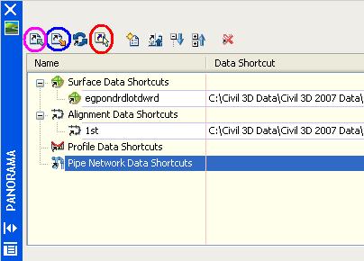
1. In a drawing that contains shortcut-able (I just created that word. Feel free to use it) objects click "General" > "Data Shortcuts" > "Edit Data Shortcuts...".

2. In the "Data Shortcuts" vista of the "Panorama" view click "Create data shortcut by selection" (4th icon, I circled it in red in the image above). Then select the object you wish use via shortcuts.

A shortcut is created but we have to export it by creating an .XML file.

3. In the "Data Shortcuts" vista of the "Panorama" view click "Export data shortcuts to file" (2nd icon, I circled it in blue in the image above). Then Name .XML file.

Now, the shortcut is available for use in another drawing. We now need to create a data reference

4. In a drawing where we wish to use a data shortcut click "General" > "Data Shortcuts" > "Edit Data Shortcuts...".

5. In the "Data Shortcuts" vista of the "Panorama" view click "Import data shortcuts to file" (1st icon, I circled it in magenta in the image above). Then select the .XML file created in step 3.

6. In the "Data Shortcuts" vista of the "Panorama" select the imported shortcut to create a reference for and then click "Create reference" (5th icon, I did not circle it in the image above).

a reference to the shortcut-ed object is then created.

We still get data synchronization messages as before. Remember this can be done without a project.

Friday, April 28, 2006

Civil 3D 2007 - New Features Workshop


One of the very useful items that I refer to often is the "New Features Workshop" this is a Flash based interface that provides information about what was introduced in Civil 3D 2007. This is similar to what AutoCAD has had available for several releases.

The interface is broken down into four sections with multiple topics and subtopics (topics are listed below, but not the many subtopics):

Create
Survey Data
Alignments and Profiles
Pipe Networks
Points
Surfaces
Analyze
Survey Data
Design Evaluation
Grading Tools
Share
Project Management
Export Data
Produce
Labels and Label Styles
Profile and Profile View Labels
Reports Manager


I had hoped to post this yesterday, but I was out doing training all day. What do you know, this was also mentioned during today's Civil 3D Webcast.

Saturday, April 15, 2006

Bootcamp Day Five - Three Homeruns

Thursday was my fifth and final day at bootcamp. It turned out to be my favorite one.

Why? Well, Autodesk hit three homeruns with me. One for each of the subjects that I covered that day.

HOMERUN #1
Pipes: The additions to pipes were excellent. New rules for both pipes and structures. Structure properties that include pipe inverts that can be edited. Rules can be reapplied at my choosing. Create a network from a pline. Create an alignment from a network. Import LDT pipe runs. Interference checking for collisions or clearance (COOL!). New grips in profile.

HOMERUN #2
Corridors: Lots here too. Many new spiral types. Constrained profiles (similar to horizontal alignments, Fixed, Floating, Free). Floating parabolic curves can now end a profile. Three new transparent commands (profile station from plan view, profile station and elevation from plan view, and profile station and elevation from plan view and point). Profile geometry point can now be labeled in plan views. Customizable markers replace hard-coded ones. Quick profiles, which can include the baseline geometry itself. Two new profile bands: Sectional data and Pipe Network data. Corridors regions can have styles (outlines). Graphical edit can be done. Individual sections can be edited. Corridor surfaces are true surfaces on Prospector tab. 16 new subassemblies. Two new tables: Total Volumes, Materials.

HOMERUN #3
General Drafting: We will now have a Toolbox tab to the Toolspace. This will include reports, but can include custom created tools. Text masking can be added to ALL labels, they can also have a draw order specified. There is now a NOTE label for any text item. We can label basic lines and curves. Reference text in labels can be created from any combination of object(s). Expressions allow us to due math computation with object data (EXCELLENT!!!). We will be able to copy label components. Drag-and-Drop styles will now prompt to Overwrite or Rename. And perhaps my favorite of all EDIT INDIVIDUAL LABEL TEXT VALUES.

It was a very useful and educational week. As you can see there is much to learn, absorb, and incorporate into our habits. That being said, I am sure glad to be home.

I'll be back soon with more detailed posts.

Wednesday, April 05, 2006

LandXML Revisited

What is Land XML? LandXML is a non-proprietary data standard created by a consortium of industry partners to share (import/export) "civil engineering data".

What type of data? Currently, LandXML 1.0, supports Cogo Points, Point Groups, Surfaces, Watersheds, Parcels, Alignments, Alignment Profiles, Alignment Cross Sections, and Pipe Networks. Shortly, 1.1 will addtionally support survey and corridors model data.

How do we use it? In Civil 3D from the "General" menu pulldown select "Import LandXML..." or "Export LandXML..."

What can we do with it? It can be used for any of the following:

1. To transfer data from a supported software application to another supported application (like LDt to Civil 3D).

2. To convert data from imperial units to metric or vice versa (automatically).

3. To globally translate/rotate coordinates (via settings).

4. To archive data at important milestones.

5. To generate reports about civil objects/data (via LandXML Reporting).

6. To allow 3D viewing of civil objects/data in a LandXML viewer (such as Autodesk Envision 8).

Six years after in was introduced it is amazing that MANY groups that would clearly benefit from the use of LandXML do not know of it's existance. Many people have dropped the ball on this one.

For example, I have used LandXML to export civil data from corrupt Civil 3D drawings and then imported the data into a clean new drawing. Problem solved.

Click on the title of this post to get to the LandXLM.org website and see examples, list of support software, and other facts.

I am revisting this topic for a few reasons. The first is because I am adding information to it. The second is because when someone does a "SEARCH THIS BLOG", via the button in the upper left hand corner, for any topic of interest, the search mechanism only goes back one year and the original post was on Feb. 14, 2005 (a little more than 1 year ago). Thirdly, because it has been one of the most viewed posts of all time (within this blog of course). Lastly, I am revisiting this subject because LandXML 1.1 is within days (weeks?) of being ratified and it will include additional capabilities.

Wednesday, March 29, 2006

Anthony's Thoughts

Today, many resellers attended a webcast that described what will be available for us to refer to, and what is in the box (Civil 3D 2007), that can be used to learn, teach, and guide.

One segment of the webcast presented by Anthony Governanti, Technical Marketing Manager for Autodesk, was the "Wicked Cool Stuff" according to him.

The following is his list (in no particular order):

Text masking! Available in all labels!
Expressions – add calculations to any label
Reference text (that can use...)
---Alignments
---Profiles
---Parcels
---Surfaces
General Note (object)
Quick Profile
DWF Preview for Project Data
Grading Feature Line tools (3D polyline tools and more)
Grading that works!
---Inside corner cleanup
---Projection to surface
Graphical Corridor Editing
New Subassemblies
---Retaining walls
---Channels
---Pipe trench
---Many more
New templates
---National CAD Standards (NCS) based
---Extended to include Civil 3D specific objects
---Includes styles to replicate LDT output
Too much to list!

Although, much of this information has been discussed here and elsewhere, it was certainly very useful for me to see Anthony's highlight reel.


PS. I want to thank Anthony for his OK to use his list.

Wednesday, March 01, 2006

Civil 3D 2007


As Autodesk introduces the NEW family of 2007 products (shipping in the next month or two) there will be lots to talk about. Here we will focus of course on Civil 3D 2007. What will be there? What will not? I will mention a few general topics today with detailed posts in the near future.

Lets begin.

One of the most obvious additions to Civil 3D is the entirely new Survey functionality and the survey observation object.

The Project environment will now be managed by the core data management capabilities of Autodesk Vault. It will allow for the sharing of:

Points
Surfaces
Alignments
Profiles
Pipe Networks (NEW)
Survey Data (NEW)

Corridors will create named surfaces directly. We will no longer have to export non-associated surfaces. We will also be able to select an existing polyline as a corridor boundary (cool). There will be new subassemblies.

Profiles will now be element-based (free, floating, fixed). This allows for similar constraints as horizontal alignments.

Grading Feature Lines will be controlled by a new set of tools which include the ability, similar to LDt, to create offsets with elevational differences.

Quick sections will be able to be created from AutoCAD objects.

We will be able to create a Pipe Network from a polyline and create an alignment from an existing pipe network. Pipe interference detection will be possible.

Styles management will include the ability to Merge, Copy, or Rename any duplicates found during drag-and-drop operations.

Labels will be able to contain data from various object types in our models. We will be able to include expressions (formulas) in a label style. The labeling of lines, arcs and polylines with style based labels will be possible. I am confident that many will appreciate that masks will be able to be added to labels to hide object behind the label.

We will be able to reset a Point's elevations based on an existing surface. Changing an individual point's rotation angle graphically will be possible.

LandXML 1.1 support for survey and corridor data will help matters.

These are just a few of the enhancements that caught my eye. These plus those found in AutoCAD 2007 and Map 3D 2007 (because Civil 3D is built on top of these products) will give us lots benefit from.

OK, that is enough for now. As I said, I hope to add comments and details in the coming days, and weeks, as time permits.

Thursday, December 22, 2005

3DDWFPublish and Transparent Surfaces


Here are a couple of things that may brighten someone's Christmas.

First, the 3DDWFPUBLISH command allows us to create a Design Web Format (DWF) file of our three-dimensional models. The process is quick and easy.

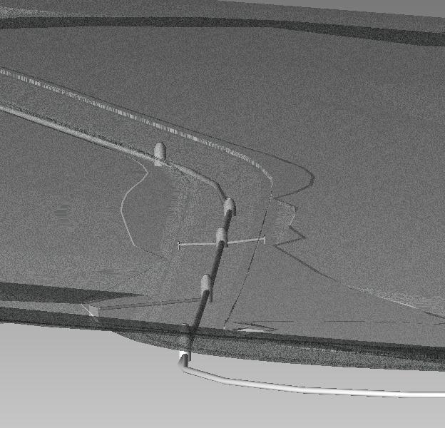
Second, in Autodesk DWF Viewer or Autodesk DWF Composer when you look at a 3D DWF you can choose components and either "Hide" them or make them "Transparent". This can be useful when needing to see a pipe network. Just make the surface transparent.

Happy Holidays!

Wednesday, November 09, 2005

Hot Fix 2 Available!

Hot Fix 2 is now available. It fixes a few items related to:

Pipe networks
grading to Surfaces from shortcuts
labeling Alignments from shortcuts

Select the title of this post to get to download page.

Monday, October 24, 2005

Improving Civil 3D Performance by Adsk

The following information is straight from the Autodesk Knowledge Base about Civil 3D 2006. It offers suggestions on how to improve performance with Civil 3D 2006.

1. Disable the Rebuild Automatic option for Surfaces and Corridors.
2. Change styles to limit the objects displayed in the drawing.
3. Use data shortcuts to reduce the amount of data in a working drawing.
4. Copy project files located on a network drive to a local drive.
5. Use the Cache model tab and the all layout tabs option on the System tab in the Options dialog box.
6. Increase Autosave timings on the Open and Save tab in the Options dialog box.
7. Change the value of the INDEXCTL variable to 0 (zero).
8. Turn off the Dynamic Input methods and selection previews.

The title of this post takes you right to the actual document.

Friday, October 14, 2005

Map 3D Mini Demonstrations

Not all Civil 3D users know that it is built on top of Map 3D which itself is built on top of AutoCAD. This means that the capabilities of Map 3D are available to Civil 3D users.

For those users that do not know much about Map 3D the title of this post is linked to an Autodesk webpage that contains ten 1-3 minute mini demonstrations showing some of the Map 3D capabilities. Two that are of particular interest are:

Drawing Cleanup
3D Surfaces

Drawing Cleanup because it can greatly increase the users ability to fix drawings with errors, and 3D surfaces because Map 3D surfaces are the same as Civil 3D surfaces.

If nothing else a user should know about the bells and whistles even if they will never use them. Although, with some progressive thinking and a little bit of initiative users may see the usefulness for a whistle here or a bell there.